Magnetic head assembly having a rotational arm for electrically connecting the magnetic head to an external circuit and methods of manufacturing the same

a magnetic head and head assembly technology, applied in the direction of maintaining the head carrier alignment, recording information storage, instruments, etc., can solve the problems of complex connection operation, defects in connection, and inability to work with the connection condition observed

Inactive Publication Date: 2004-08-19
TDK CORPARATION
View PDF6 Cites 6 Cited by
  • Summary
  • Abstract
  • Description
  • Claims
  • Application Information

AI Technical Summary

Benefits of technology

[0012] In a method of wiring a magnetic head assembly of the invention, the arm side-wiring member and the external side-wiring member are fixed sandwiching a conductive adhesive member having anisotropic conductivity and connected. The conductive adhesive member has conductivity only in the direction of overlapping. This prevents conduction of each adjacent terminal even if there is a plurality of terminals in the first connecting portion of the arm side-wiring member or the second connecting portion of the external side-wiring member. The connection of the arm side-wiring member and the external side-wiring member on a predetermined exterior surface of the rotational arm facilitates the connection process.

Problems solved by technology

In such a method of connecting by ultrasonic welding or solder fusion, however, the connecting operation is complicated.
This results in defects in connection.
It makes it impossible to work with the connecting condition observed.
This results in poor workability.

Method used


Image

  • Magnetic head assembly having a rotational arm for electrically connecting the magnetic head to an external circuit and methods of manufacturing the same
  • Magnetic head assembly having a rotational arm for electrically connecting the magnetic head to an external circuit and methods of manufacturing the same
  • Magnetic head assembly having a rotational arm for electrically connecting the magnetic head to an external circuit and methods of manufacturing the same

Examples


Embodiment Construction

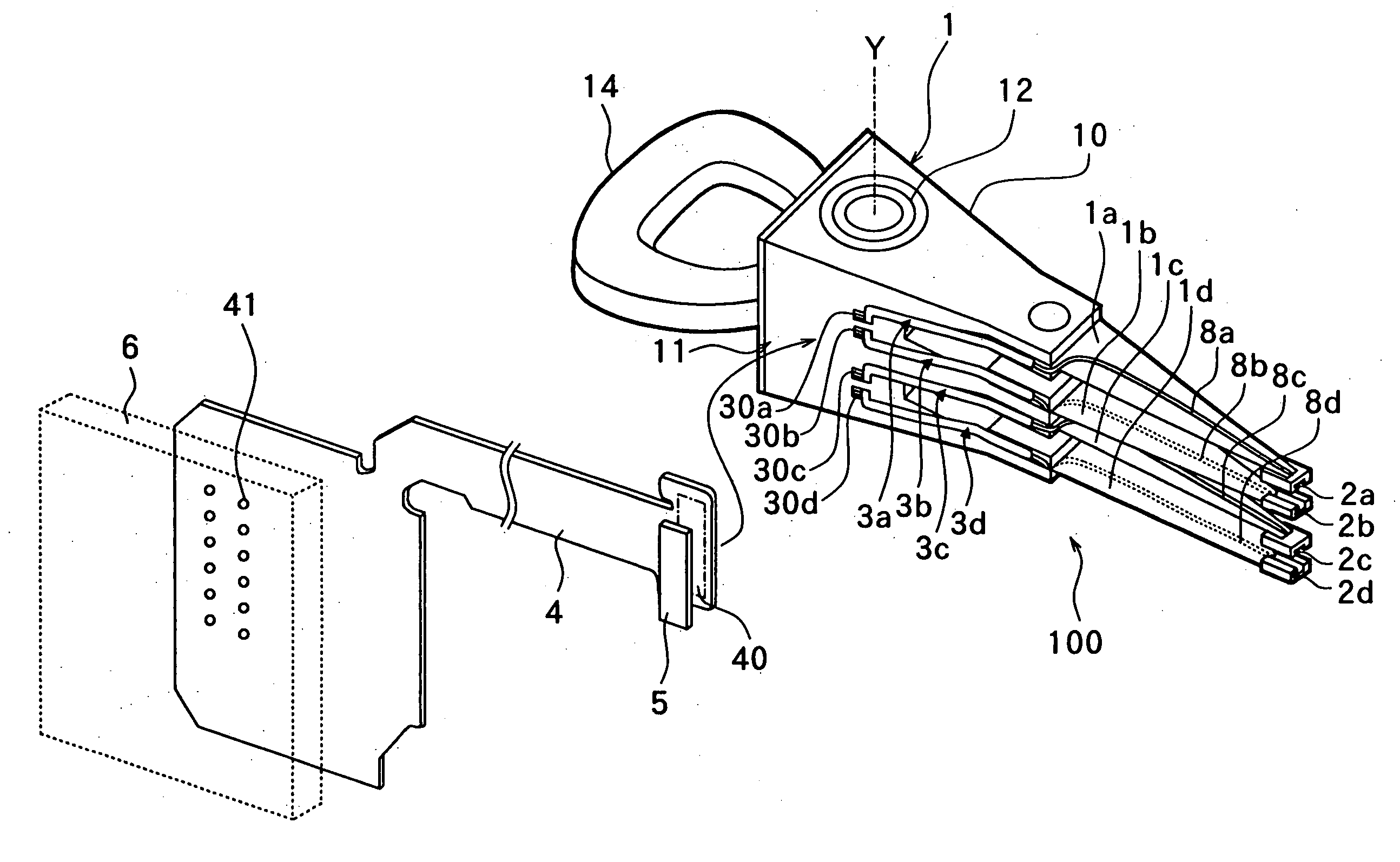
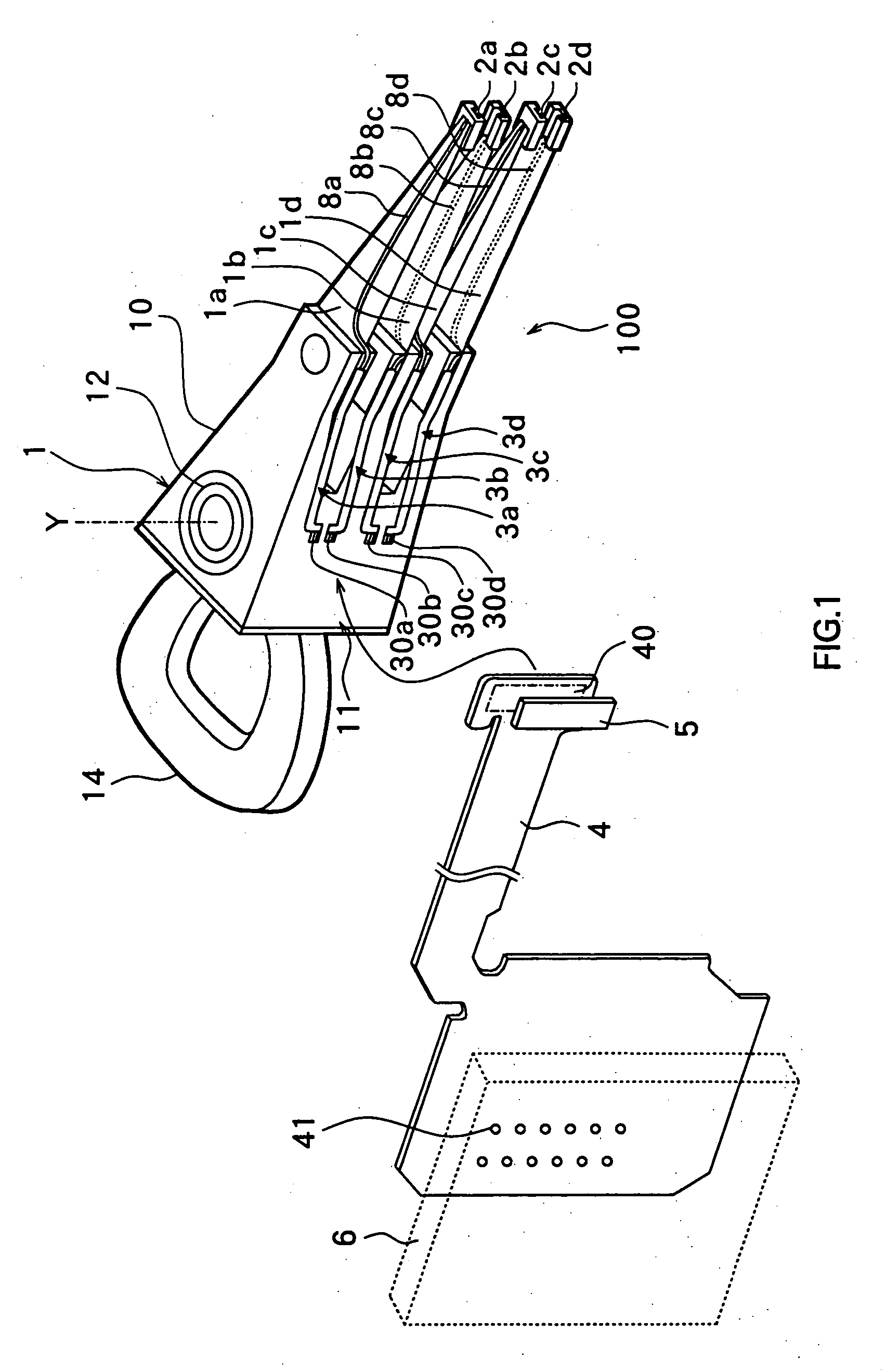
[0060] As described above, according to the method of wiring a magnetic head assembly of this embodiment, the connecting portion 40 of the external side FPC board 4 and the connecting terminals 30a to 30d of the relay FPC boards 3a to 3d are overlapped and fixed by the anisotropic conductive tape 5. This enables to connect a plurality of wirings of both connecting portions in a single step. As a result, defects in connection are reduced and connecting process is simplified as compared to the individual connection by each wiring. This also prevents peeling of gold plate formed on, for example, the external side FPC board 4 without using ultrasonic welding. The connecting portion 40 of the external side FPC board 4 is connected to the connecting terminals 30a to 30d of the relay FPC board 3a to 3d on the side 11 of the arm body 10. This enables to operate with observing the connecting condition and therefore the workability is improved.

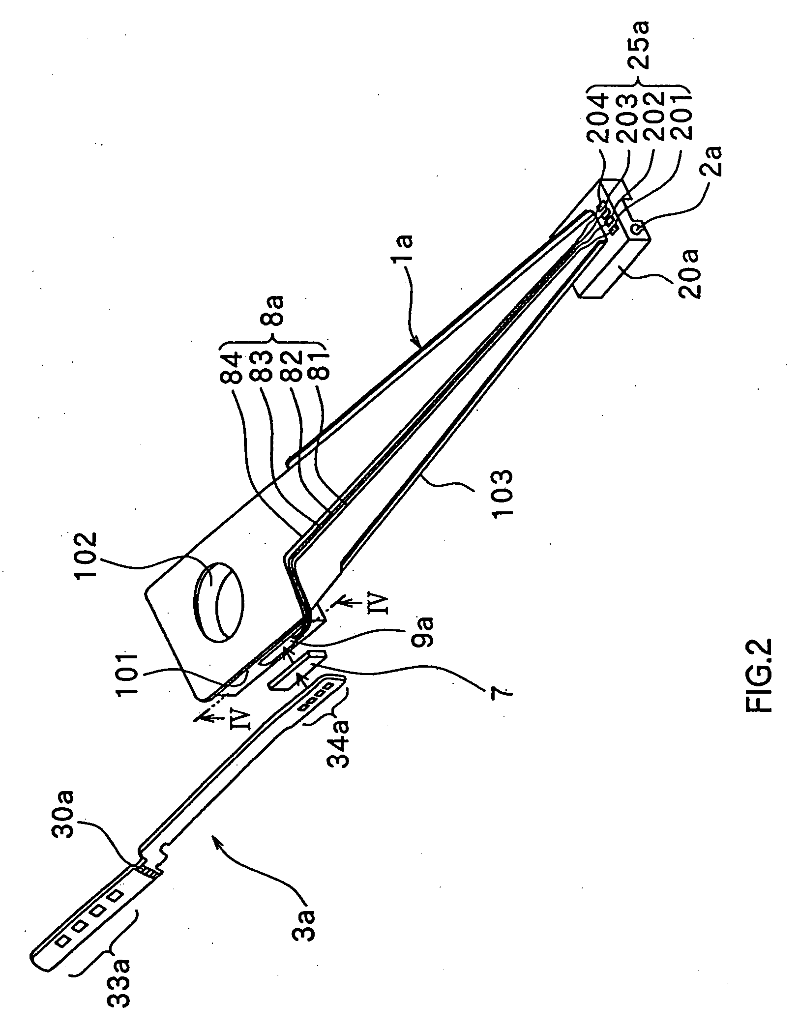
[0061] The relay terminals 34a to 34d of the rela...


PUM

PropertyMeasurementUnit
thicknessaaaaaaaaaa
cure temperatureaaaaaaaaaa

Abstract

A connecting portion of the external side FPC board connected to a control circuit provided outside of a magnetic head assembly and connecting terminals of arm side FPC boards respectively connected to magnetic heads are overlapped with an anisotropic conductive tape having anisotropic conductivity in the direction of thickness in between. The anisotropic conductive tape is applied pressure between the connecting portion and the connecting terminals with heating to a temperature of, for example, 150° C. and is set. As a result, the connecting portion and the connecting terminals are connected. The anisotropic conductive tape has anisotropic conductivity only in the direction of thickness so that conduction of wirings adjacent each other is prevented although a plurality of wirings is formed on the connecting portion and the connecting terminals.

Description

[0001] This is a divisional application of co-pending U.S. application Ser. No. 09 / 694,010 filed Oct. 23, 2000. The entire disclosure of the prior application is hereby incorporated by reference in its entirety.[0002] 1. Field of Invention[0003] The present invention relates to a magnetic head assembly using for a magnetic disk apparatus or the like, to a method of manufacturing the same and to a method of wiring the same using for signal transmission between a magnetic head and external.[0004] 2. Description of Related Art[0005] Generally, in magnetic disk apparatus, a magnetic head assembly reads out / writes information on a magnetic disk of recording medium. A magnetic head assembly comprises a rotational arm rotating along a recording surface of a magnetic disk. On the tip of the rotational arm, a magnetic head for reading / writing information of magnetic disk is mounted.[0006] In order to enable signal transmission between a control circuit provided on the body portion of a magne...

Claims


Application Information

Patent Timeline
Patent Type & Authority Applications(United States)
IPC IPC(8): G11B5/48G11B5/60G11B21/02G11B21/16H05K3/32H05K3/36
CPCG11B5/4846H05K3/361H05K3/323
Inventor YAGI, ICHIRO
Owner TDK CORPARATION
Why Eureka
Try Eureka