Wireless communication

a technology of wired communication and backhaul infrastructure, applied in the field of wireless communication, can solve the problems of prohibitively expensive installation and maintenance of wired backhaul infrastructure, the need to provide wires of communication quality, etc., and achieve the effect of effectively coordinating the transmission of the transmission, avoiding interference, and avoiding the high installation and maintenance costs of wired ds

Active Publication Date: 2004-08-19
APPLE INC
View PDF8 Cites 155 Cited by
  • Summary
  • Abstract
  • Description
  • Claims
  • Application Information

AI Technical Summary

Benefits of technology

0034] Advantageously, use of a wireless Distribution System (DS) avoids the high installation and maintenance costs of a wired DS.
0035] Use of synchronised Transit Link Control allows the nodes to schedule their transmissions such that they can avoid interference to and from each other. It enables distant nodes to effectively coordinate their transmissions for the purposes of eliminating mutual interference without needing explicitly to communicate directly with each other.
0036] Additionally, it enables nodes to schedule their transmissions such that they can avoid interference from non-system interferers.
0037] By dividing up the transmission bandwidth into a number of slots according to a selection of transmission parameters, it provides a greater opportunity for nodes to find a transmission slot which is suitable for use.
0038] Utilisation of the multiple degrees of freedom of wireless communication, (e.g. beam, frequency, polarisation, burst time) mitigates interference and maximises system capacity.

Problems solved by technology

However, the problem with this wired approach is that wires of communications quality need to be provided to each AP, and interconnected via wired switches / hubs / routers etc.
However, in other environments the installation and maintenance of this wired backhaul infrastructure could be prohibitively expensive.

Method used


Image

  • Wireless communication
  • Wireless communication
  • Wireless communication

Examples


Embodiment Construction

[0050] Embodiments of the present invention are described below by way of example only. These examples represent the best ways of putting the invention into practice that are currently known to the Applicant although they are not the only ways in which this could be achieved.

[0051] Referring to FIGS. 2-6, there is shown an example of the present invention.

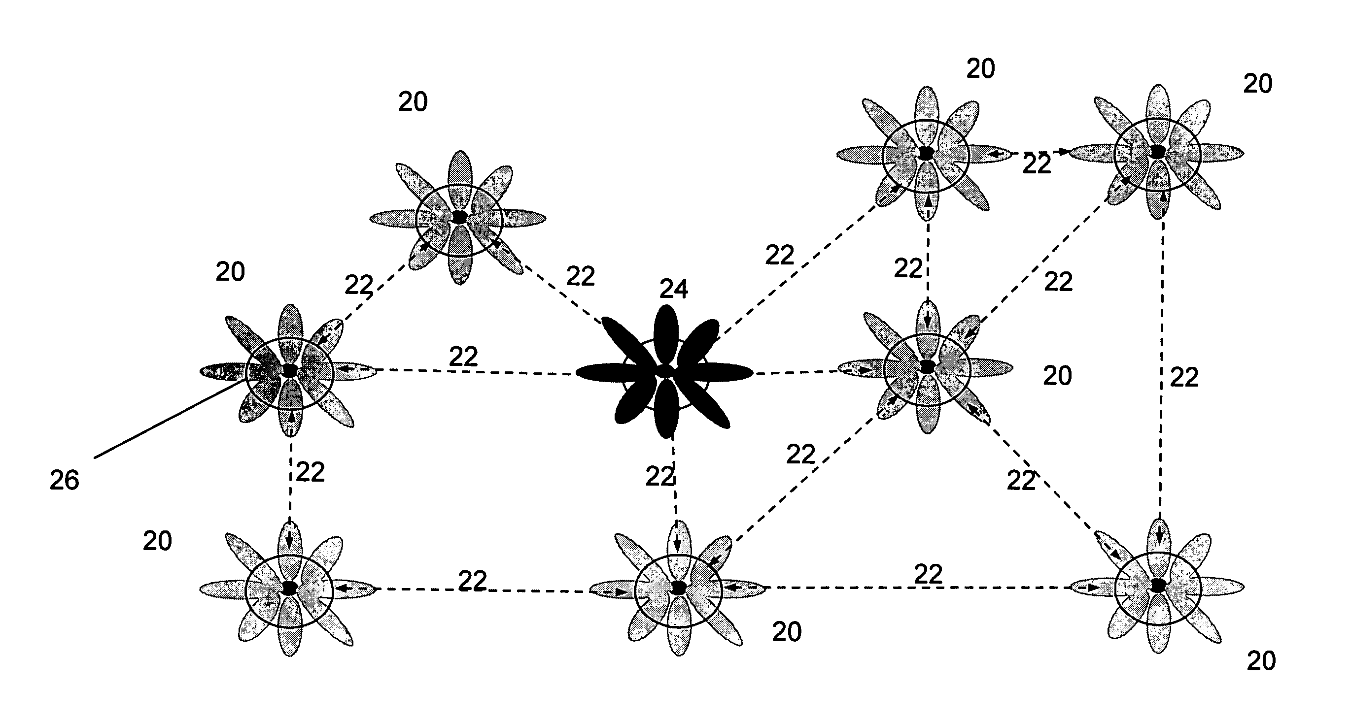
[0052] FIG. 2 shows a schematic diagram of a CAN. The network comprises a number of Wireless Access and Routing Points (WARPs) 20, interconnected by wireless links 22. This CAN therefore uses a wireless `Distribution System` (DS). The WARPs perform a number of functions, including acting as access points (APs) for connection to mobile nodes (MNs) such as PDAs. The area of coverage of the access link (AL), which is the link from the AP to a MN is shown schematically in FIG. 2 by the circles 26. The WARPs are wirelessly connected to each other and to the Network Access Point (NAP) 24. The WARPs also act as Transit Nodes (TNodes), for...


PUM


Abstract

The invention is directed to a method of synchronising transmission between two nodes in a wireless network. The method comprises the steps of obtaining an expected interference profile for each node; and agreeing a synchronised transmission schedule between the nodes, where the expected interference profile of the or each node meets predetermined criteria.

Description

[0001] This application is the full utility filing of U.S. provisional application No. 60 / 447,646 filed on Feb. 14, 2003, from which the present application claims priority and which is incorporated herein by reference.[0002] This patent application is related to the following Provisional patent applications filed in the U.S. Patent and Trademark Office, the disclosures of which are expressly incorporated herein by reference:[0003] U.S. Patent Application Serial No. 60 / 446,617 filed on Feb. 11, 2003 and entitled "System for Coordination of Multi Beam Transit Radio Links for a Distributed Wireless Access System" [15741][0004] U.S. Patent Application Serial No. 60 / 446,618 filed on Feb. 11, 2003 and entitled "Rendezvous Coordination of Beamed Transit Radio Links for a Distributed Multi-Hop Wireless Access System" [15743][0005] U.S. Patent Application Serial No. 60 / 446,619 filed on Feb. 12, 2003 and entitled "Distributed Multi-Beam Wireless System Capable of Node Discovery, Rediscovery ...

Claims


Application Information

Patent Timeline
Patent Type & Authority Applications(United States)
IPC IPC(8): H04B7/005H04L12/56
CPCH04W56/002H04B7/2678H04B7/0617H04B17/345H04W84/12
Inventor BEVAN, DAVIDBALNES, STEVEN
Owner APPLE INC
Why Eureka
Try Eureka