Touch panel display device

a display device and touch panel technology, applied in the field of touch panel display devices, can solve the problems of display failure and increase production cost, and achieve the effect of reducing cost and easy production

Inactive Publication Date: 2004-08-26
AMTEK SYST
View PDF7 Cites 45 Cited by
  • Summary
  • Abstract
  • Description
  • Claims
  • Application Information

AI Technical Summary

Benefits of technology

0011] The display part and the remaining part of the upper casing are integrally formed without the need of any additional film or opening. The touch panel display device of the invention therefore is easily produced with a reduced cost.

Problems solved by technology

1. The upper casing 1 must be formed with the central opening 11 and the film 12, which increases the production cost.
2. Usually, there is a gap or slit between the opening 11 and the film 12 through which dust or moisture easily penetrates, which may cause a display failure.

Method used


Image

  • Touch panel display device
  • Touch panel display device
  • Touch panel display device

Examples


Embodiment Construction

[0022] Wherever possible in the following description, like reference numerals will refer to like elements and parts unless otherwise illustrated.

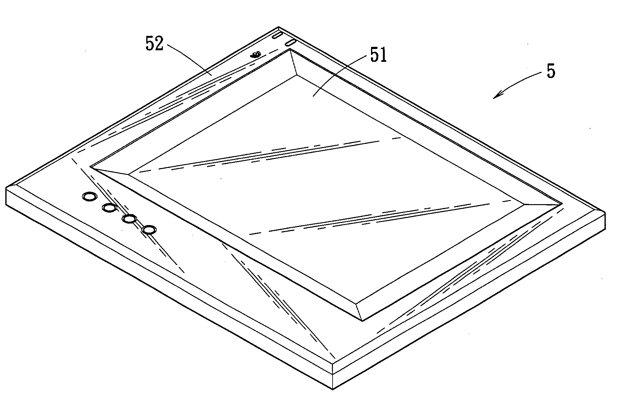
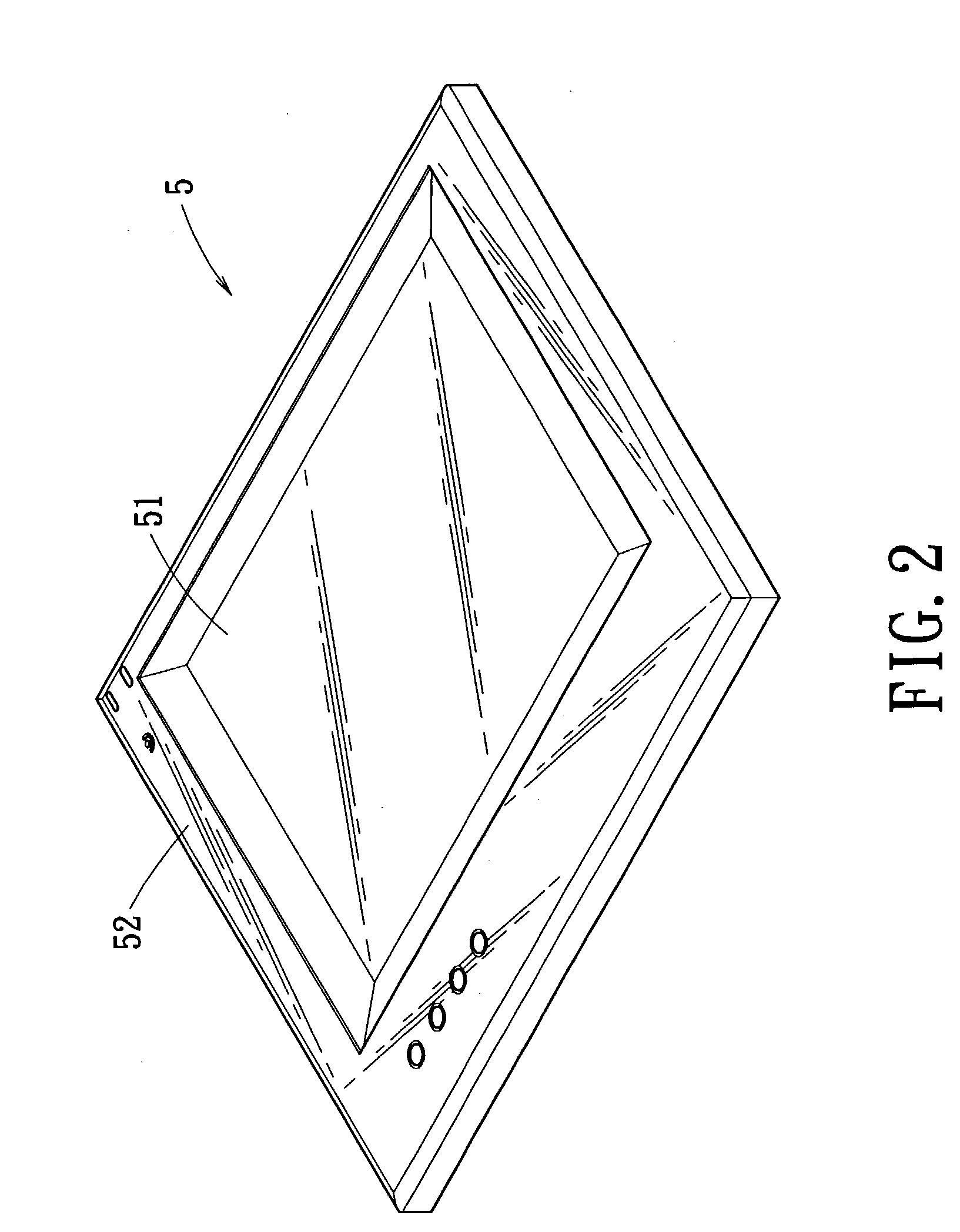
[0023] FIG. 2 through FIG. 4 show an upper casing 5 of a touch panel display device according to one embodiment of the invention. FIG. 5 through FIG. 7 illustrate the assembly of the touch panel display device according to one embodiment of the invention.

[0024] Referring FIG. 2 through 4, an upper casing 5 including a display part 51 and a peripheral part 52 is integrally formed in a single body. The display part 51 is mounted in a central opening and is surrounded by the peripheral part 52. Either the whole upper casing 5 is transparent as shown in FIG. 2, or only the display part 51 is transparent and a remaining part 53 of the upper casing 5 is painted. As a result, the painted remaining part 53 may be opaque or semi-transparent.

[0025] As illustrated in FIG. 4, which is a cross-sectional view of FIG. 3, the display part 51 is integrally...


PUM


Abstract

A touch panel display device that is easily produced with a lower cost and has moisture-proof and dust-proof properties includes an upper casing, a lower casing, a touch control module and a circuit board. The upper casing includes a display part and a remaining part surrounding the display part. The lower casing is mounted corresponding to the upper casing to define a space therein. The touch control module is located under a bottom of the upper casing in the defined space. The circuit board is located between the touch control module and the lower casing in the defined space. The display part and the remaining part of the upper casing are integrally formed in a single body with no gap or slit there between. A bottom of the display part is correspondingly attached to a top of the touch control module.

Description

[0001] 1. Field of the Invention[0002] The invention relates to a touch panel display device and, more particularly, to a touch panel display device that is provided with a touch control module by means of which a user manually operates the touch panel display device.[0003] 2. Description of the Related Art[0004] Referring to FIG. 1, a conventional touch panel display includes an upper casing 1, a lower casing 2, a touch panel control module 3 and a circuit board 4. The upper casing 1 has a central opening 11.[0005] The upper and lower casing 1 and 2 are mounted corresponding to each other to define a space for receiving the touch control module 3 and the circuit board 4. The touch control module 3 is located directly under the opening 11 of the upper casing. A film 12 is further attached on the touch control module 3 and is exposed through the opening 11. The circuit board 4 is mounted between the touch control module 3 and the lower casing 2.[0006] When a user manually touches the...

Claims


Application Information

Patent Timeline
Patent Type & Authority Applications(United States)
IPC IPC(8): G06F3/048G09G5/00
CPCG06F3/0488
Inventor LEE, WANG-TSAI
Owner AMTEK SYST
Why Eureka
Try Eureka