Hair dryer with minus ion generator

a hair dryer and generator technology, applied in the direction of curling tongs, curling irons, hair drying, etc., can solve the problems of difficult to achieve style congenial to the user's taste, difficult to efficiently perform hair styling, and general difficulty in carrying out hair styling of dried hair

Active Publication Date: 2004-09-09
MATSUSHITA ELECTRIC WORKS LTD
View PDF5 Cites 61 Cited by
  • Summary
  • Abstract
  • Description
  • Claims
  • Application Information

AI Technical Summary

Benefits of technology

[0013] According to the hair dryer of the present invention, since a hot air flow and a cold air flow with the minus ions can be simultaneously provided from the air outlet, it is possible to remarkably improve a minus-ion effect on hair, as compared with the conventional hair dryer for simply providing the hot air flow with the minus ions. In addition, since the hair dryer can present a layered air flow composed of the hot air flow and the cold air flow with minus ions, sulfur-to-sulfur bonding of hair in an undesired hair style can be broken by heat energy of the hot air flow of the layer air flow, and new sulfur-to-sulfur bonding can be created in a desired hair style by cooling the hair with the cold air flow of the layer air flow. Therefore, it is possible to efficiently fix the user's hair tousled with sleep or naturally wave hair, and also easily provide a hair style congenial to the user's taste within a shortened time period, as compared with a case that after hair drying is finished by use of the hot air flow, hair styling is performed by use of the cold air flow with minus ions, or that the hair styling and the hair drying are concurrently performed by use of the hot air flow with minus ions.

Problems solved by technology

By the way, the hot air flow is useful to efficiently dry wet hair, but hair styling of the dried hair is generally hard to carry out, so that there is a case that a hair style congenial to the user's taste is not obtained.
As a result, it becomes difficult to efficiently perform hair styling, while maintaining the moist and smooth hair.
However, in this case, it will take an extended time period to finish the hair styling.

Method used


Image

  • Hair dryer with minus ion generator
  • Hair dryer with minus ion generator
  • Hair dryer with minus ion generator

Examples


first embodiment

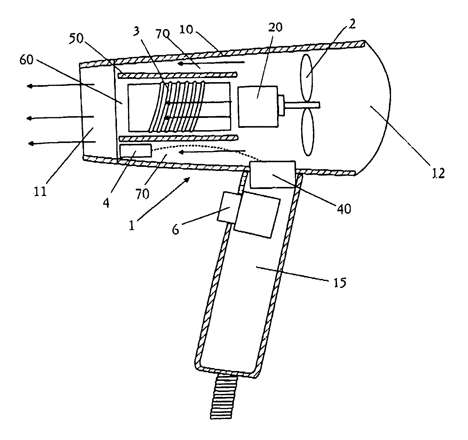
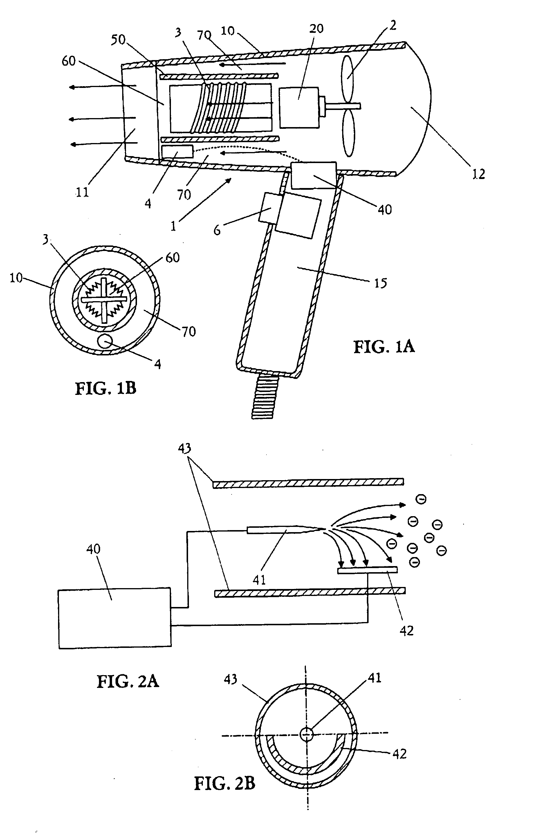
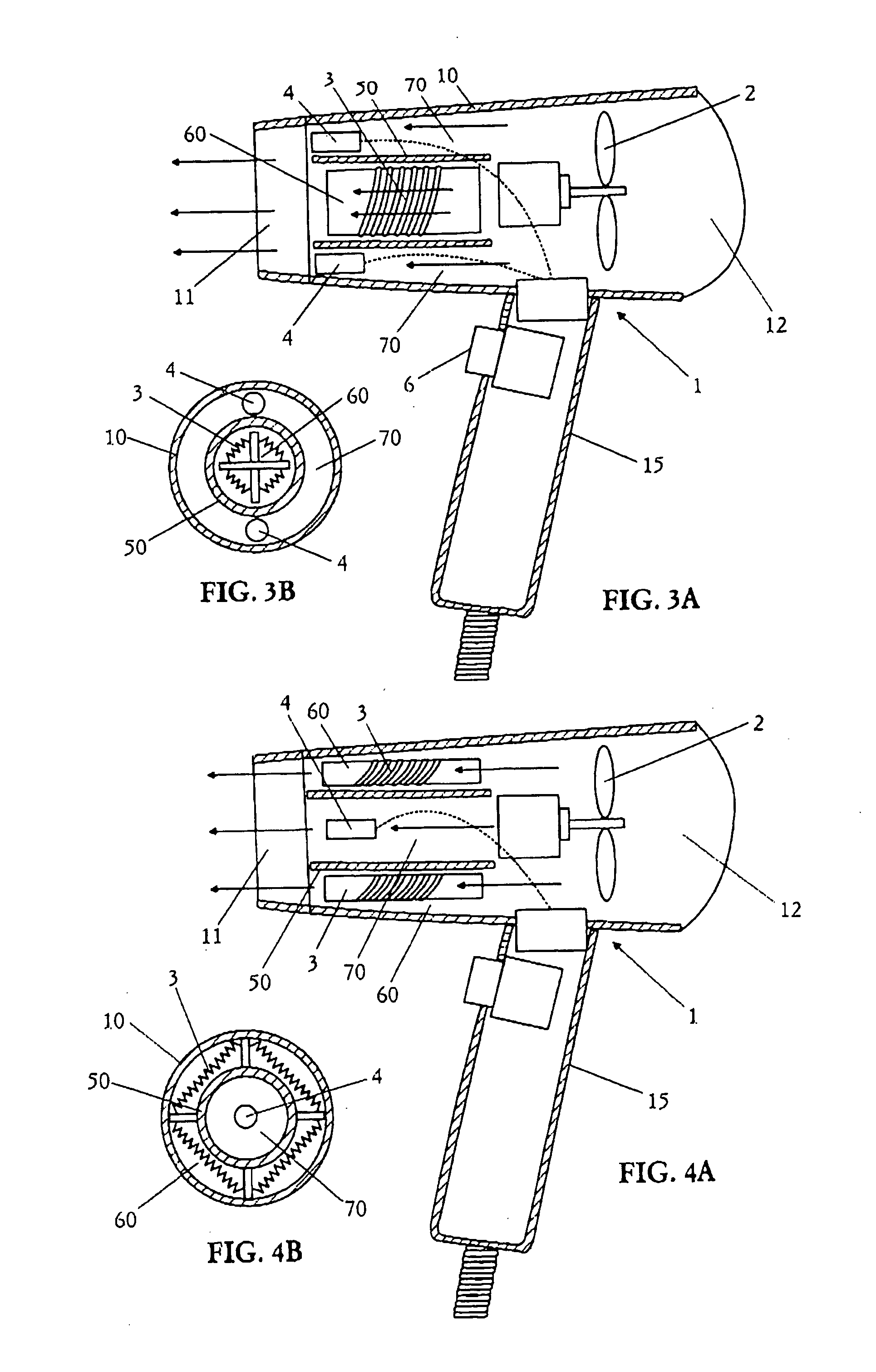
[0042] As shown in FIGS. 1A and 1B, a hair dryer 1 of the first embodiment is mainly composed of a hollow housing 10 having an air inlet 12 at its one end and an air outlet 11 at its opposite end, and a grip housing 15 having switches 6 and extending downwardly from the hollow housing.

[0043] In the housing, a fan 2 is disposed between the air inlet 12 and the air outlet 11, and a pair of first and second air flow channels (60, 70) are defined, which extend toward the air outlet 11, and separated from each other by a partition wall. In this embodiment, the partition wall is formed by a tubular member 50, which is disposed in the housing 10 such that the first air flow channel 60 is provided by an inner space of the tubular member, and the second air flow channel 70 is provided by an clearance between an inner surface of the housing and an outer surface of the tubular member. A heater 3 is disposed in the first air flow channel 60, and a minus-ion generator 4 is disposed in the second...

second embodiment

[0055] A hair dryer according to the second embodiment is substantially the same as the hair dryer of the first embodiment other than the following features. Therefore, the duplicate explanation is omitted.

[0056] In the subject embodiment, as shown in FIG. 9, an air sucked from the air inlet 12 into the housing 10 by the fan 2 is supplied only to the first air flow channel 60, in which the heater 3 is placed. An air to be supplied into the second air flow channel 70, in which the minus ion generator 4 is disposed, is sucked from a supplemental air inlet 13 formed in the housing 10 at a different position from the air inlet 12. In this case, a partition wall for separating the first air flow channel from the second air flow channel is composed of a horizontal wall 52 and a vertical wall 53. Therefore, the first air flow channel 60 is defined between the top surface of the horizontal wall 52 and the inner surface of the housing 10, and the second air flow channel 70 is defined by a sp...

third embodiment

[0058] A hair dryer according to the third embodiment is substantially the same as the hair dryer of the first embodiment except for the following features. Therefore, the duplicate explanation is omitted.

[0059] The present embodiment is, as shown in FIG. 10, characterized in that the housing 10 has a minus-ion outlet 80 formed at a different position from the air outlet 11 to eject minus ions generated by the minus ion generator 4. That is, an accommodation room 81 for the minus ion generator 4 is completely separated from the first and second air flow channels (60, 70). Therefore, the minus ions generated by the minus ion generator 4 diffuses into the outside air through the minus-ion outlet 80, and then join with the cold air flow ejected from the air outlet 11. In this case, since the layered air flow provided from the air outlet 11 is composed of the core of the hot air flow and the external layer of cold air flow with minus ions around the core from the air outlet, the minus i...


PUM


Abstract

A hair dryer is provided, which includes a housing having an air outlet, fan disposed in the housing, a pair of air flow channels extending toward the air outlet in the housing, a partition wall for separating the channels from each other, heater disposed in only one of the channels, and a minus-ion generator disposed in the other channel. The partition wall is formed by a tubular member, which is disposed in the housing such that one of the channels is provided by an inner space of the tubular member, and the other channel is provided by a clearance between an inner surface of the housing and an outer surface of the tubular member. Therefore, it is possible to simultaneously provide a cold air flow with minus ions and a hot air flow from the air outlet, and thereby efficiently perform hair styling.

Description

[0001] 1. Field of the Invention[0002] The present invention relates to a hair dryer with a minus ion generator, which has the capability of simultaneously providing a cold air flow with minus ions and a hot air flow to efficiently perform hair styling as well as hair treatment.[0003] 2. Disclosure of the Prior Art[0004] In the past, it is said that an air flow with minus ions is effective to perform hair styling, while keeping the moisture content of hair. Therefore, various kinds of hair dryers with minus ion generator have been proposed.[0005] For example, Japanese Utility Model Registration No. 3086680 discloses a hair dryer 1M with a minus ion generator 4M, as shown in FIG. 17. This dryer includes a tubular housing 10M, in which an air flow channel 60M is defined, so that air sucked from an air inlet 12M provided at one end of the housing is ejected from an air outlet 11M provided at the other end thereof. In the air-flow channel 60M of the housing 10M, a fan 2M, heater 3M, and...

Claims


Application Information

Patent Timeline
Patent Type & Authority Applications(United States)
IPC IPC(8): A45D1/00A45D7/00A45D20/00A45D20/04A45D20/10A45D20/12
CPCA45D20/10A45D2200/202A45D20/12
Inventor SAIDA, ITARUTAKASHIMA, KIYOSHIKAMADA, KENJITAKANO, HIROYUKIITO, KENGOMIZUTA, AKINOBUNAKAGAWA, TAKASHI
Owner MATSUSHITA ELECTRIC WORKS LTD
Why Eureka
Try Eureka