Acceleration detector and passive safety device

a technology of acceleration detector and safety device, which is applied in the direction of pedestrian/occupant safety arrangement, electrical apparatus, vehicle components, etc., can solve the problems of increasing costs and weight, etc., and reducing the installation space of acceleration detector, reducing costs and weight, and reducing impact at the time of abutment

Inactive Publication Date: 2004-09-09
MITSUBISHI ELECTRIC CORP
View PDF21 Cites 3 Cited by
  • Summary
  • Abstract
  • Description
  • Claims
  • Application Information

AI Technical Summary

Benefits of technology

0046] Thus, the installation space of the acceleration detector can be reduced, and the increases in costs and weight can be suppressed. In addition, even if the displacement amount of the mass member is made large when severe impact acceleration is applied, and the first and second mass members are thereby abutted on each other, impacts at the time of the abutment can be reduced. As a result, damage to the mass member and the other components can be prevented, making it possible to maintain reliability.
0047] According to the acceleration detector of the invention, the spring member is provided between the first and second mass members to be prevented from being fully compressed when one of the first and second mass members is displaced along the shaft body toward the other of the first and second mass members, and the buffer members of the first and second mass members are abutted on each other.
0048] Thus, the installation space of the acceleration detector can be reduced, and the increases in costs and weight can be suppressed. In addition, by suppressing the characteristic change of the spring member caused by the fully compressed state of the spring member, the accuracy of acceleration detection can be maintained.

Problems solved by technology

Consequently considerable space is required for disposition of the device which results in increases in costs and weight as well as other problems.

Method used


Image

  • Acceleration detector and passive safety device
  • Acceleration detector and passive safety device
  • Acceleration detector and passive safety device

Examples


first embodiment

[0064] (First Embodiment)

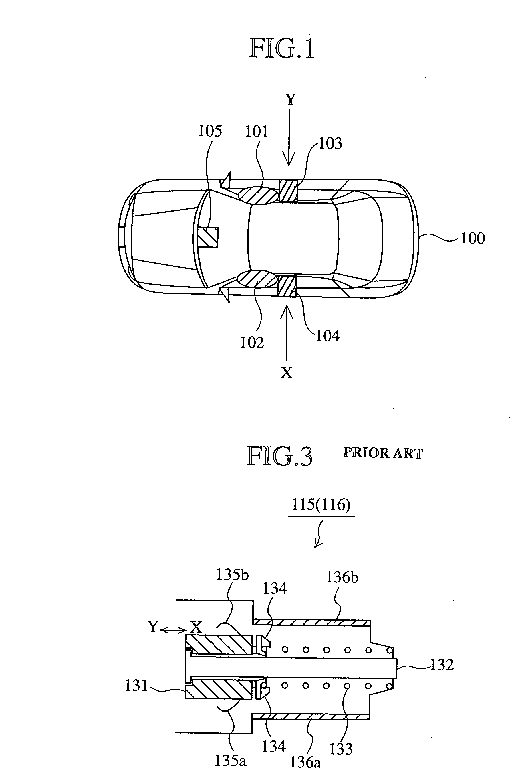
[0065] FIG. 4 is an arrangement configuration view, showing positions for arranging an air bag and a sensor provided to detect acceleration applied to a car, in the passive safety device of a vehicle, to which the acceleration detector of a first embodiment is applied.

[0066] In FIG. 4, a reference numeral 1 denotes a car main body; 2 a vehicle right side air bag arranged on the indoor side at the right of the travelling direction of the car; and 3 a vehicle left side air bag arranged on the indoor side at the left of the travelling direction of the car. A reference numeral 4 denotes a vehicle right side sensor (vehicle side part sensor) arranged, for example inside the right side of the vehicle, to detect side-on collision on the right of the travelling direction of the car; and 5 a vehicle left side sensor (vehicle side part sensor) arranged, for example inside the left side of the vehicle, to detect side-on collision on the left of the traveling direction ...

second embodiment

[0088] (Second Embodiment)

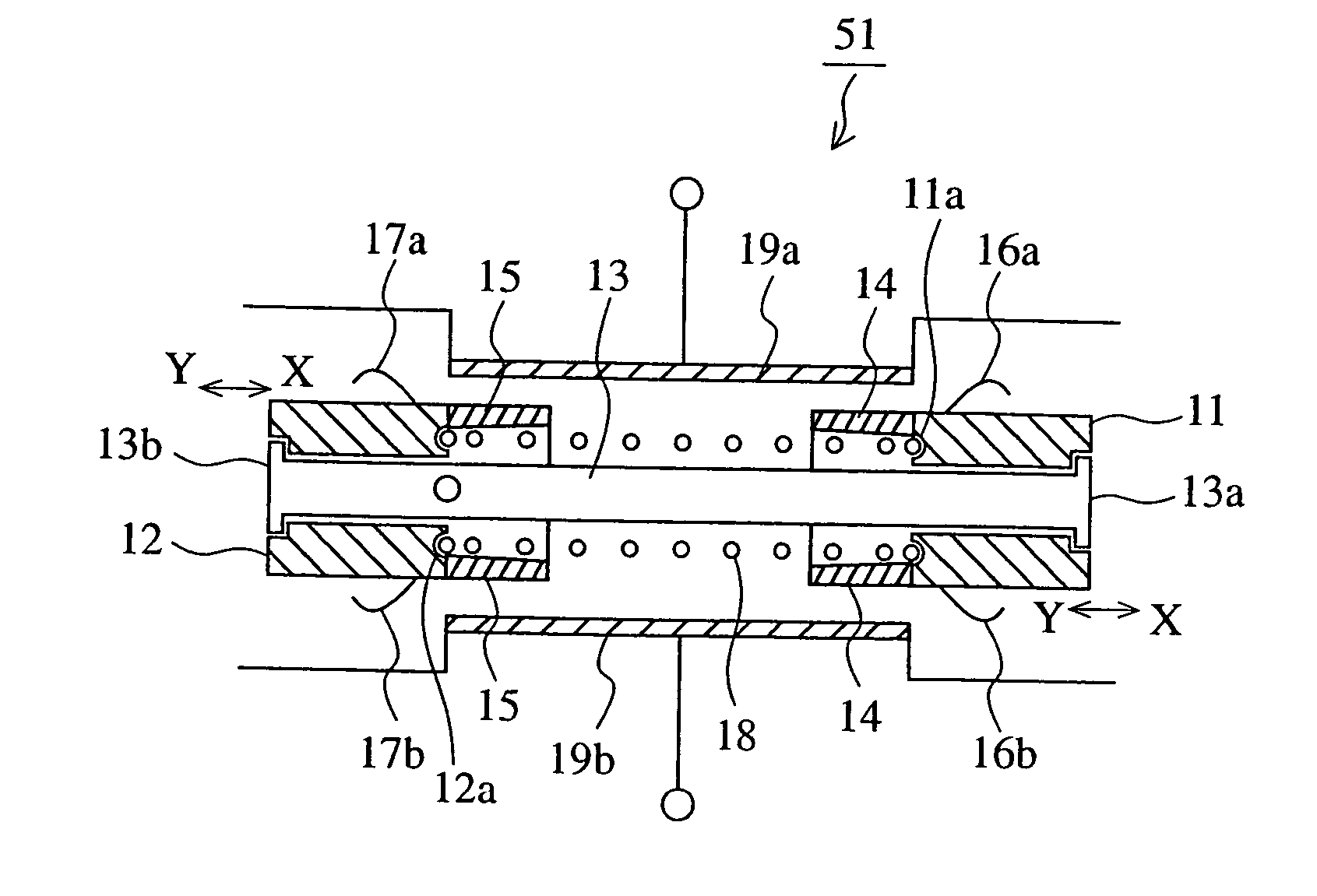
[0089] FIG. 7 is a sectional structural view showing the acceleration detector of a second embodiment of the invention. In FIG. 7, portions identical or similar to those shown in FIG. 5 are denoted by like reference numerals, and description thereof will be omitted. Also, in the second embodiment, the configuration of the first embodiment described above with reference to FIGS. 4 and 6 is applied.

[0090] In FIG. 7, a reference numeral 61 denotes the acceleration detector of the second embodiment arranged in the car compartment sensor unit 6; 37 a reed switch (magnetic switch detection means, and detection means); and 38 and 39 the output terminals of the reed switch 37. This reed switch 37 corresponds to the electric contact 51a of the first embodiment described above with reference to FIG. 6.

[0091] A reference numeral 41 denotes a first mass member for detecting impact acceleration caused by side-on collision on a left side of the car in the travelling dire...

third embodiment

[0101] (Third Embodiment)

[0102] FIG. 8 is a perspective structural view showing an acceleration detector according to a third embodiment of the invention. In the third embodiment, the configuration of the first embodiment is described above with reference to FIGS. 4 and 6.

[0103] In the drawing, a reference numeral 91 denotes an acceleration detector; 71 a weight (pendulum type mass body) having, for example an elliptic shape in section, supported by a shaft 76 so as to swing clockwise and counterclockwise; 72 a first plate-like bending contact member (movable piece, and detection means) made of a stainless plate (phosphor bronze plate may be used) for example as a resilient material, abutted on the belly of the weight 71, and bent in the direction of the arrow X following the counterclockwise swinging of the weight 71 around the shaft 76; and 73 a contact (detection means) provided in the outer surface of the tip part of the first bending contact member. A reference numeral 74 denot...


PUM


Abstract

By using an acceleration detector 51 incorporating mass members respectively capable of detecting impact acceleration applied from different directions, the impact acceleration applied on the vehicle from the different directions is detected with one acceleration detector. The installation space of the acceleration detector in a car compartment sensor unit 6 is reduced. Moreover, the increases in costs and weight are suppressed.

Description

[0001] This application is the national phase under 35 U.S.C. .sctn. 371 of PCT International Application No. PCT / JP00 / 01682 which has an International filing date of Mar. 17, 2000, which designated the United States of America and was not published in English.[0002] 1. Field of the Invention[0003] This invention relates to an acceleration detector, which can detect acceleration in a different direction by a compact structure, and a passive safety device for protecting an occupant with an air bag by using the acceleration detector. More specifically, the invention relates to an acceleration detector and a passive safety device, which are suitably used for the protection of the occupant in a car.[0004] 2. Background Art[0005] FIG. 1 is an arrangement configuration view, schematically showing the arranging positions of an air bag and a sensor for detecting acceleration applied to a car in the passive safety device of the car.[0006] In FIG. 1, a reference numeral 100 denotes a car main...

Claims


Application Information

Patent Timeline
Patent Type & Authority Applications(United States)
IPC IPC(8): B60R21/01B60R21/16B60R21/33H01H35/14
CPCB60R21/0132H01H35/147H01H35/14B60R21/33
Inventor YAMASHITA, TOSHIYUKI
Owner MITSUBISHI ELECTRIC CORP
Why Eureka
Try Eureka