Microphone array, method and apparatus for forming constant directivity beams using the same, and method and apparatus for estimating acoustic source direction using the same

Inactive Publication Date: 2004-09-09
SAMSUNG ELECTRONICS CO LTD
View PDF9 Cites 98 Cited by
  • Summary
  • Abstract
  • Description
  • Claims
  • Application Information

AI Technical Summary

Problems solved by technology

Here, the uniform arrays are less welcomed than the non-uniform arrays because even though the uniform arrays are easy to manufacture and analyze, their directivity pattern varies with respect to frequency.
Therefore, in recent years, various efforts have been made to provide a constant level of directivity using a non-uniform array structure rather than a uniform array structure.
In addition, in a case where a moving robot is a voice capture system, such as a microphone array, or the target source is moving, a look directi

Method used


Image

  • Microphone array, method and apparatus for forming constant directivity beams using the same, and method and apparatus for estimating acoustic source direction using the same
  • Microphone array, method and apparatus for forming constant directivity beams using the same, and method and apparatus for estimating acoustic source direction using the same
  • Microphone array, method and apparatus for forming constant directivity beams using the same, and method and apparatus for estimating acoustic source direction using the same

Examples


Embodiment Construction

[0053] An experiment was carried out to compare the performance of a beam forming method according to the present invention with the performance of a conventional beam forming method. For the experiment, a microphone array according to the present invention, like the one shown in FIG. 5A, and a conventional microphone array, like the one shown in FIG. 5B were used. Let us assume that a distance between the center of each of those microphone arrays used in the experiment and a target source was 3 m and a real look direction was 0.degree.. Suppose the sound source localization apparatus used in this experiment estimated a look direction as 10.degree. which is the case of a look direction error. A distance between the center of each of those microphone arrays used in the experiment and a noise source was 3 m, and a look direction was 90.degree.. Here, the beam forming apparatus was supposed to have no information on the precise location of the noise source. Fan noise was used as the no...


PUM


Abstract

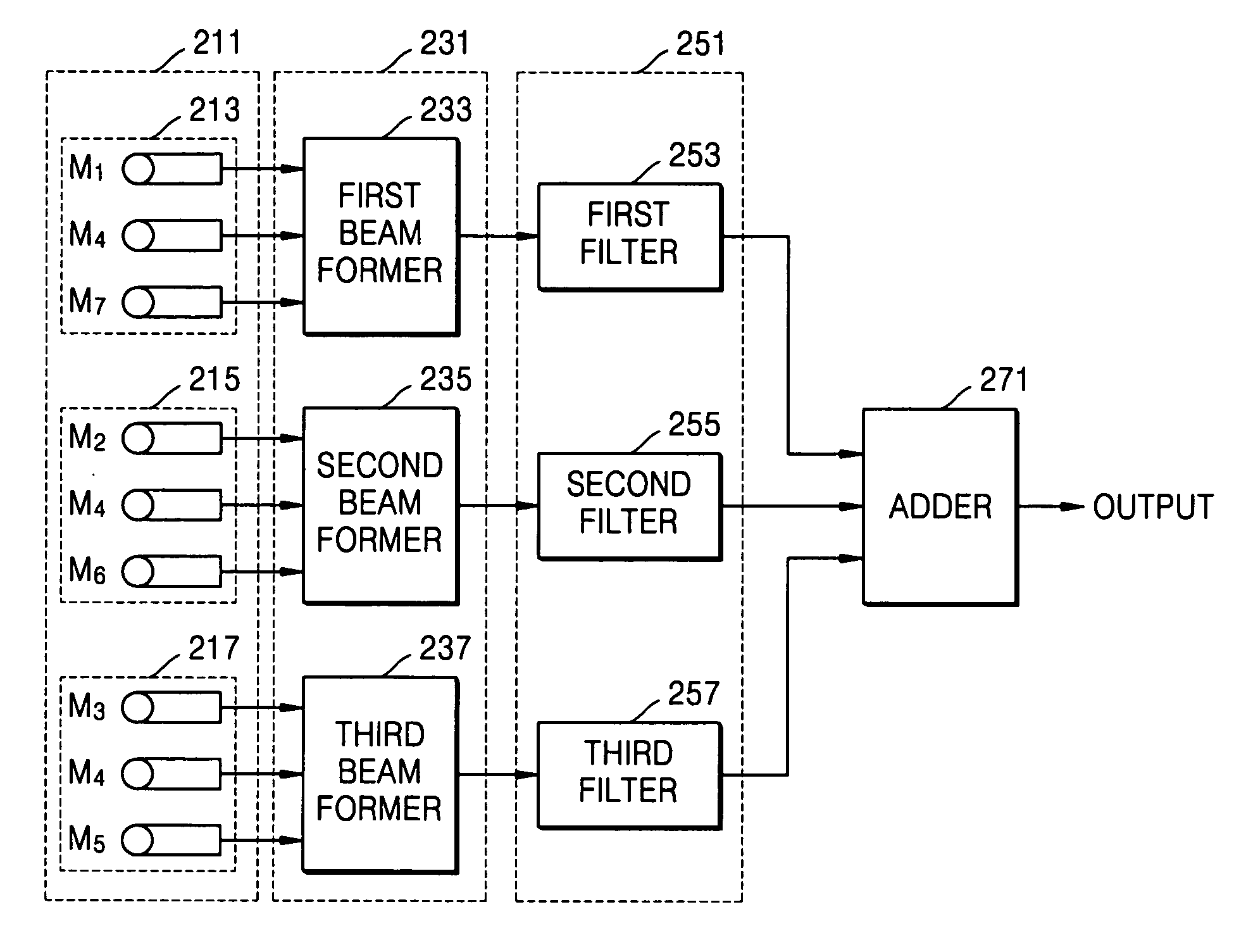
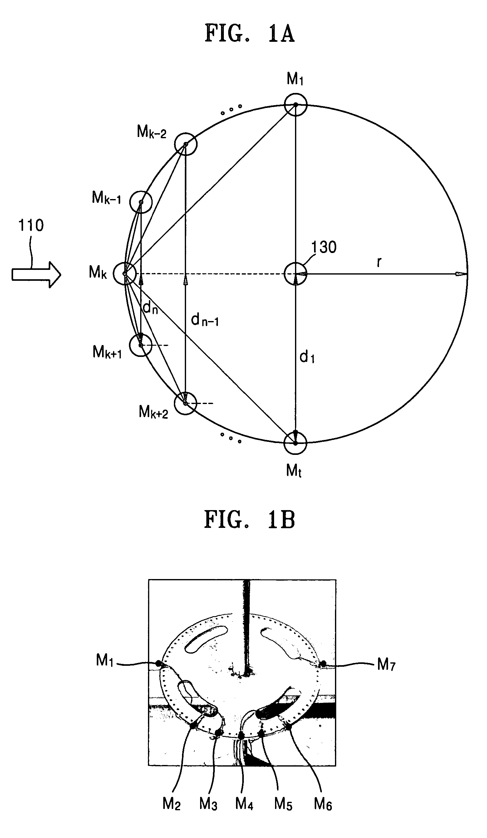
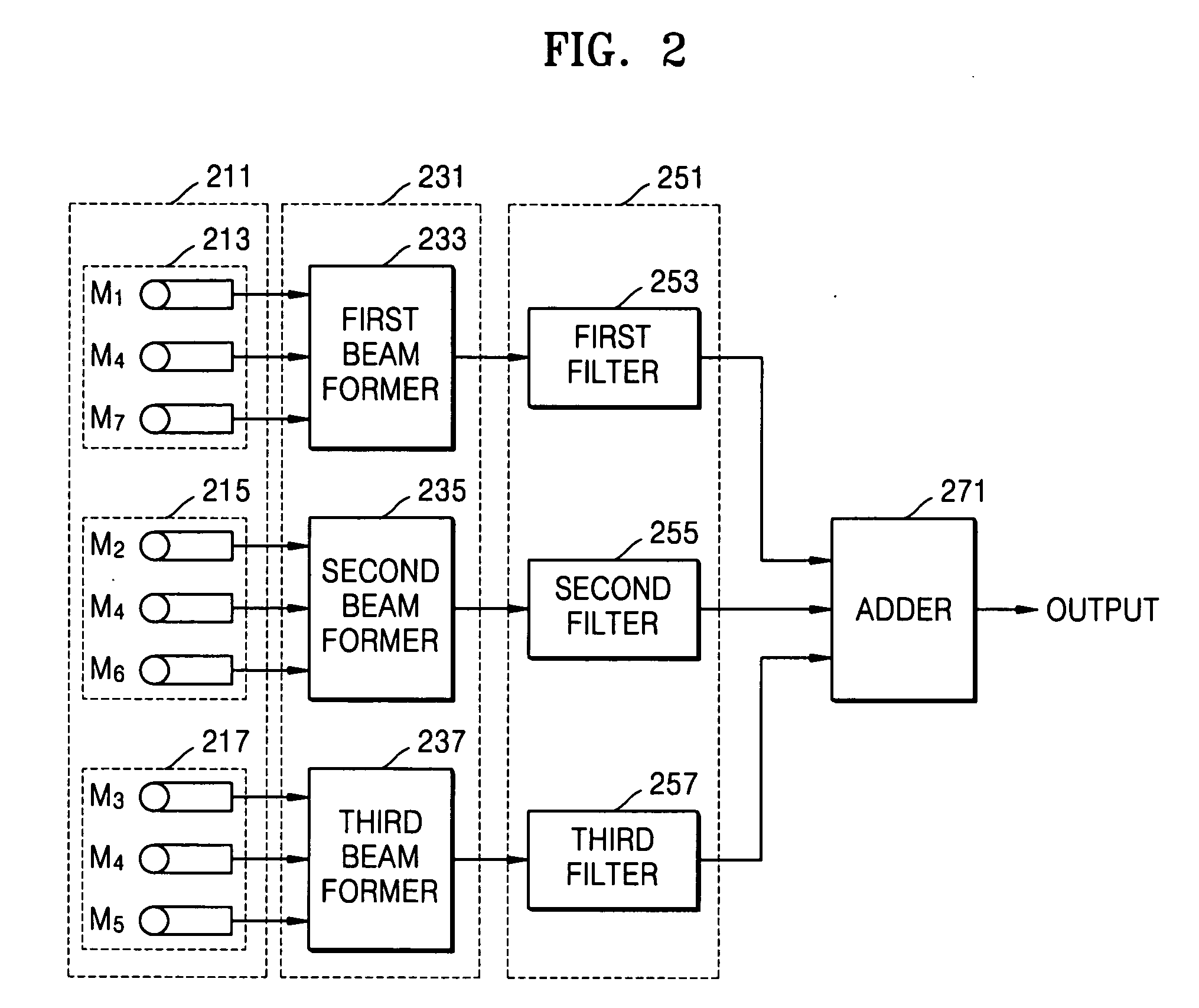
A microphone array, beam forming method and apparatus using the microphone array, and a method and apparatus for estimating an acoustic source direction using the microphone array are provided. The apparatus for forming constant directivity beams comprising: a microphone array, which is comprised of first through n-th microphone sub-arrays, wherein each of the microphone sub-arrays comprises: a first microphone placed at a predetermined location on a flat plate, which commonly belongs to each of the microphone sub-arrays; and second and third microphones placed at locations perpendicularly spaced by a predetermined segment from a straight line connecting the first microphone and the center of the flat plate, the predetermined segment being determined depending on a target frequency allotted to reach of the microphone sub-arrays, a beam formation unit receiving voice signals output from the first through n-th microphone sub-arrays and generating a beam for each of the first through n-th microphone sub-arrays; a filtering unit filtering the beams output from the beam formation unit; and an adding unit adding the filtered signals output from the filtering unit.

Description

[0001] This application claims the priority of Korean Patent Application No. 2003-14006, filed on Mar. 6, 2003, in the Korean Intellectual Property Office, the disclosure of which is incorporated herein in its entirety by reference.[0002] 1. Field of the Invention[0003] The present invention relates to audio technology using a microphone array, and more particularly, to a microphone array, a method and apparatus for forming constant directivity beams using the same, and a method and apparatus for estimating an acoustic source direction using the same.[0004] 2. Description of the Related Art[0005] Voice-related techniques, such as hand-free communications, video conferences, or voice recognition, need a robust voice capture system appropriate for an environment where noise and reverberations exist. Recently, a microphone array adopting a beam forming method capable of increasing a signal-to-noise ratio by preventing noise and reverberations from affecting desired voice signals has be...

Claims


Application Information

Patent Timeline
IPC IPC(8): G01S3/808G10L15/28H04R1/20H04R1/40H04R3/00
CPCH04R1/406H04R3/005H04R2430/25H04R2201/405H04R2430/23H04R2201/401H04R1/20
Inventor KIM, JAYWOOKONG, DONG-GEONCHOI, CHANG-KYU
Owner SAMSUNG ELECTRONICS CO LTD
Why Eureka
Try Eureka