Dynamic annular pressure control apparatus and method

a technology of annular pressure control and control apparatus, which is applied in the direction of drilling machines and methods, construction, and well accessories to achieve the effect of increasing the annular pressur

Inactive Publication Date: 2004-09-16
SHELL OIL CO
View PDF61 Cites 66 Cited by
  • Summary
  • Abstract
  • Description
  • Claims
  • Application Information

AI Technical Summary

Benefits of technology

0009] According to the present invention there is provided a drilling system for drilling a bore hole into a subterranean earth formation, wherein one may readily control annular pressure. Whereas, U.S. Pat. No. 6,352,129 utilizes a backpressure pump to pump mud back into the discharge outlet, the present invention utilizes the primary mud pump and diverts at least a portion of the mud flow to the discharge outlet to increase annular pressure.

Problems solved by technology

If the formation strength is exceeded, formation fractures will occur which will create drilling problems such as fluid losses and borehole instability.

Method used


Image

  • Dynamic annular pressure control apparatus and method
  • Dynamic annular pressure control apparatus and method
  • Dynamic annular pressure control apparatus and method

Examples


Embodiment Construction

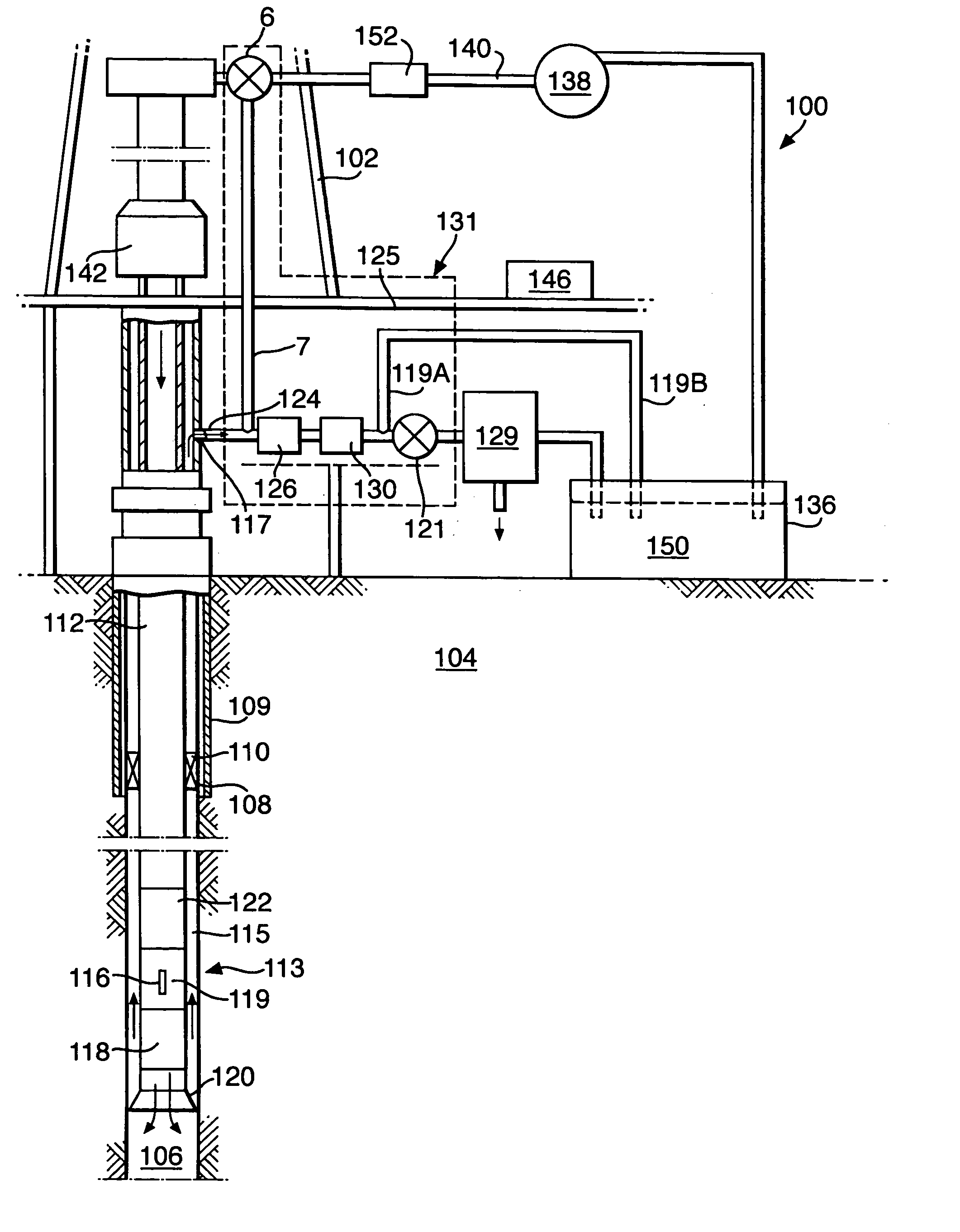
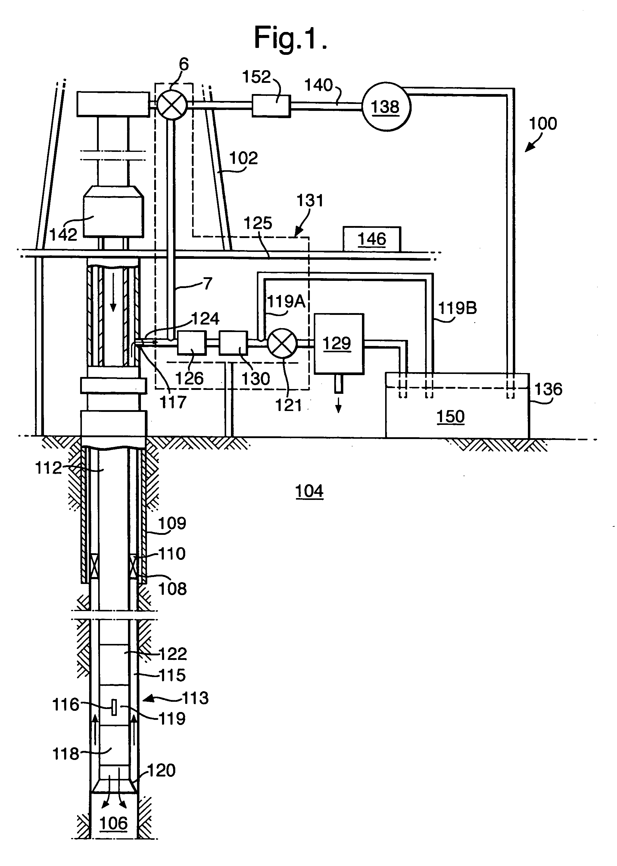
[0018] The present invention is intended to achieve Dynamic Annulus Pressure Control (DAPC) of a well bore during drilling, completion and intervention operations.

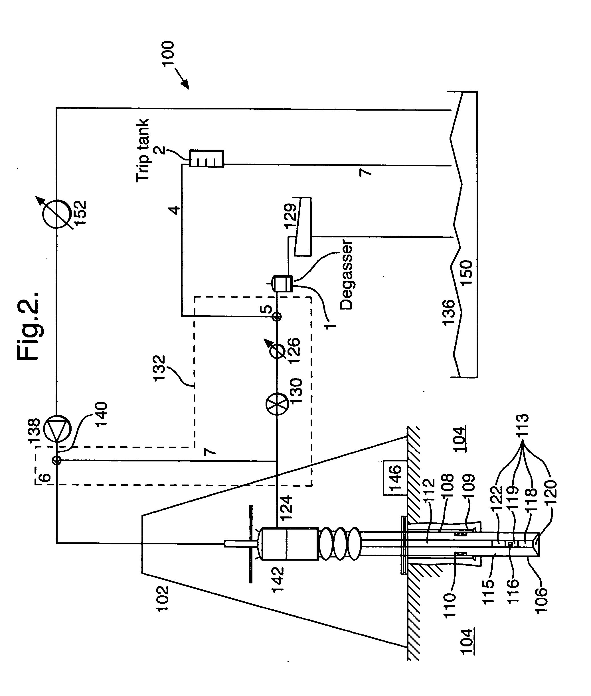
[0019] FIGS. 1 to 3 are a schematic views depicting surface drilling systems employing embodiments of the current invention. It will be appreciated that an offshore drilling system may likewise employ the current invention. In the figures, the drilling system 100 is shown as being comprised of a drilling rig 102 that is used to support drilling operations. Many of the components used on a rig 102, such as the kelly, power tongs, slips, draw works and other equipment are not shown for ease of depiction. The rig 102 is used to support drilling and exploration operations in formation 104. The borehole 106 has already been partially drilled, casing 108 set and cemented 109 into place. In the preferred embodiment, a casing shutoff mechanism, or downhole deployment valve, 110 is installed in the casing 108 to optionally shut-off...


PUM


Abstract

A drilling system for drilling a bore hole into a subterranean earth formation, wherein at least a portion of the mud flow from the primary mud pump is diverted to the mud discharge outlet, thereby creating a backpressure system to readily increase annular pressure.

Description

PRIORITY CLAIM[0001] The present application is a continuation in part of U.S. application Ser. No. 10 / 368,128, filed 18 Feb. 2003, pursuant to MPEP 201.11(a).[0002] The present invention is related to a method and an apparatus for dynamic well borehole annular pressure control, more specifically, a selectively closed-loop, pressurized method for controlling borehole pressure during drilling and well completion.BACKGROUND OF THE ART[0003] The exploration and production of hydrocarbons from subsurface formations ultimately requires a method to reach and extract the hydrocarbons from the formation. This is typically achieved by drilling a well with a drilling rig. In its simplest form, this constitutes a land-based drilling rig that is used to support and rotate a drill string, comprised of a series of drill tubulars with a drill bit mounted at the end. Furthermore, a pumping system is used to circulate a fluid, comprised of a base fluid, typically water or oil, and various additives ...

Claims


Application Information

Patent Timeline
Patent Type & Authority Applications(United States)
IPC IPC(8): E21B21/08E21B21/10E21B44/00
CPCE21B21/08E21B44/00E21B21/106E21B21/01
Inventor RIET, EGBERT JAN VAN
Owner SHELL OIL CO
Why Eureka
Try Eureka