Fuel injection device of internal combustion engine

a fuel injection device and internal combustion engine technology, applied in the direction of fuel injection apparatus, spraying apparatus, charge feed system, etc., can solve the problems of difficult to atomize the fuel of the fuel, air affecting the engine performance, and difficult to respond to the conventional atomization technology

Active Publication Date: 2004-09-16
DENSO CORP
View PDF8 Cites 32 Cited by
  • Summary
  • Abstract
  • Description
  • Claims
  • Application Information

AI Technical Summary

Benefits of technology

[0010] According to an aspect of the present invention, a fuel injection valve is formed with multiple injection holes. Therefore, positions for forming sprays injected from the respective injection holes can be adjusted arbitrarily by changing positions of the injection holes. Accordingly, the shape of a great spray formed of the sprays injected from the respective injection holes can be adjusted arbitrarily. Thus, the fuel spray in a desired shape can be formed easily. An outlet side opening of the injection hole is formed in a flattened shape having a major axis and a minor axis. Moreover, a sectional area of the injection hole gradually changes along a direction from an inlet side opening to the outlet side opening of the injection hole. Therefore, the fuel is injected as a spray in the shape of a film from the flattened outlet side opening. Therefore, liquid film splitting (splitting of the fuel spray in the shape of the film) is promoted and fuel atomization can be promoted further.
[0011] According to another aspect of the present invention, colliding means is disposed between a fuel inlet and a fuel outlet of the injection hole. The fuel flowing into the injection hole from the fuel inlet collides with the colliding means. Then, the fuel is injected from the fuel outlet. Since the fuel flowing into the injection hole collides with the colliding means, the fuel is broken into minute liquid droplets. Thus, kinetic energy of the fuel is converted into atomization energy through the collision between the fuel and the colliding means. Thus, the atomization of the fuel can be promoted further. Moreover, control of the fuel spray is facilitated owing to the colliding means.

Problems solved by technology

In the case of such a kind of engine, mixing performance between the fuel injected from the fuel injection valve and the air affects engine performance.
However, it is difficult for the conventional atomization technology to respond to the recent strengthening of the exhaust gas regulations.
Therefore, further atomization of the fuel is difficult.

Method used


Image

  • Fuel injection device of internal combustion engine
  • Fuel injection device of internal combustion engine
  • Fuel injection device of internal combustion engine

Examples


first embodiment

[0052] (First Embodiment)

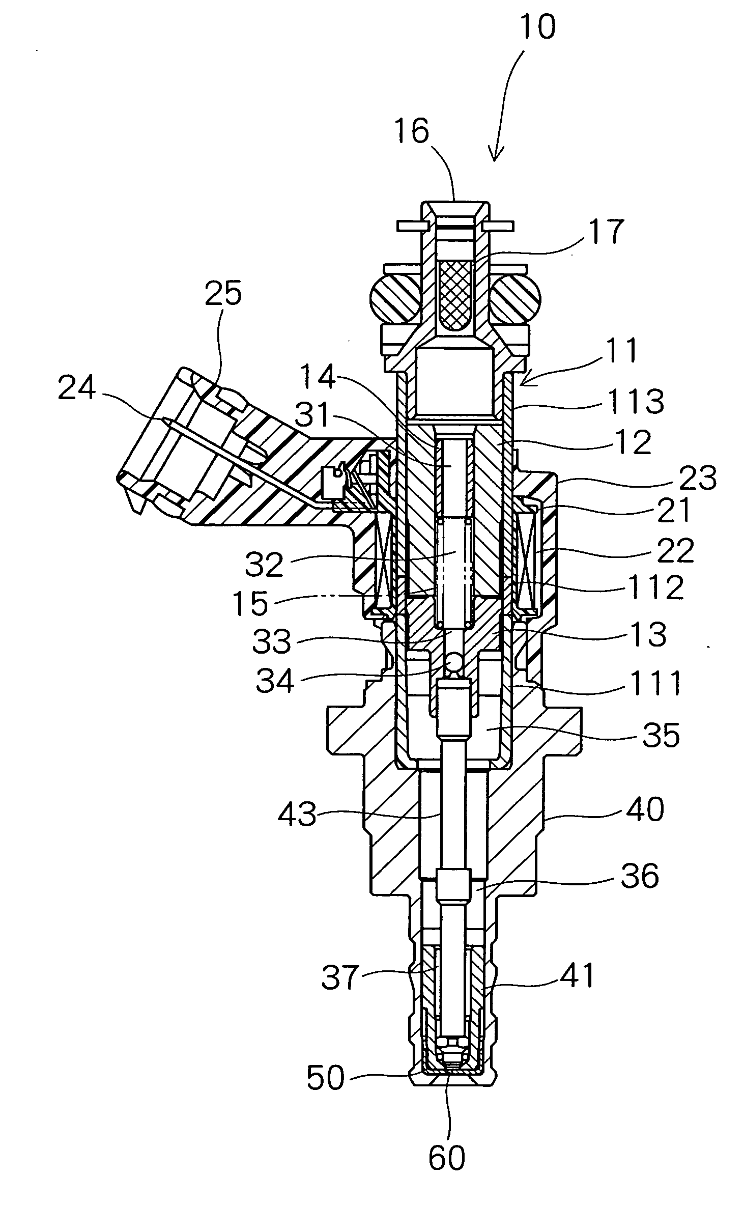
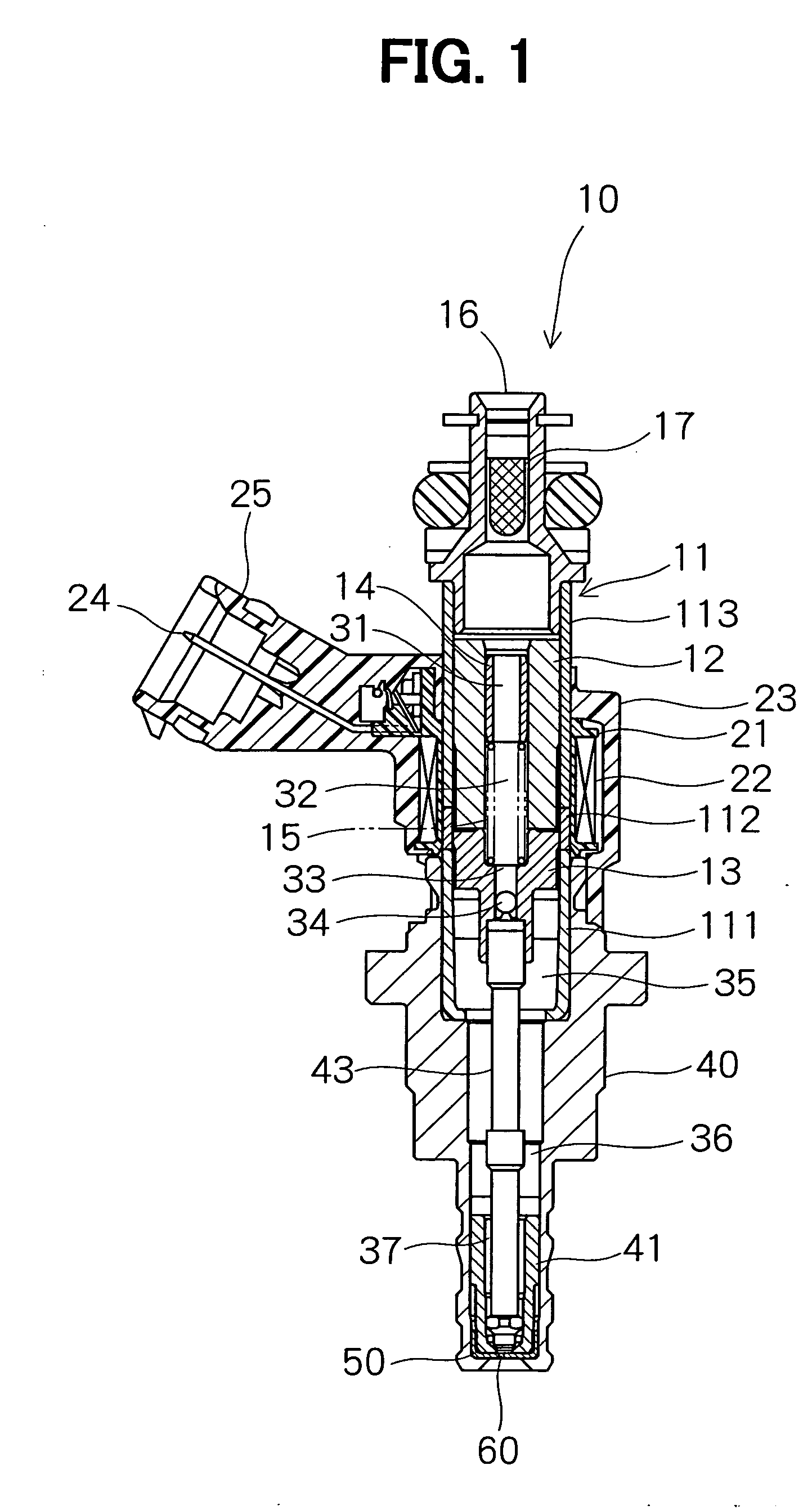
[0053] Referring to FIG. 1, a fuel injection valve (an injector, hereafter) 10 according to a first embodiment of the present invention is illustrated. The injector 10 according to the first embodiment is mounted in a cylinder head 3, which provides a combustion chamber 2 of a gasoline engine 1. More specifically, the injector 10 of the first embodiment is used in the direct-injection type gasoline engine 1, which injects the fuel directly into the combustion chamber 2. The injector 10 can be used in a premix type gasoline engine, which injects the fuel into intake air flowing through an air intake pipe 4 connected to the combustion chamber 2. The injector 10 can be used in a diesel engine also.

[0054] As shown in FIG. 1, a housing 11 of the injector 10 is formed in a cylindrical shape. The housing 11 has a first magnetic portion 111, a non-magnetic portion 112 and a second magnetic portion 113, which are disposed coaxially with each other. The non-magnetic p...

second embodiment

[0074] (Second Embodiment)

[0075] Next, an injection hole plate 50 of an injector 10 according to the second embodiment will be explained based on FIG. 6.

[0076] As shown in FIG. 6, an inlet side opening 71 of an injection hole 70 is formed in the shape of a flattened ellipse having a major axis and a minor axis. Likewise, an outlet side opening 72 of the injection hole 70 is formed in the shape of a flattened ellipse having a major axis and a minor axis. Therefore, a section of the injection hole 70 perpendicular to its central axis is formed in the shape of an ellipse. The major axis of the inlet side opening 71 is shorter than the major axis of the outlet side opening 72. The minor axis of the inlet side opening 71 is longer than the minor axis of the outlet side opening 72. Alternatively, the minor axis of the inlet side opening 71 may be equal to or different from the minor axis of the outlet side opening 72. The sectional area of the injection hole 70 gradually changes along a d...

third embodiment

[0078] (Third Embodiment)

[0079] Next, an injection hole plate 50 of an injector 10 according to the third embodiment will be explained based on FIGS. 7 to 8B. In the third embodiment, an inlet side opening 81 of an injection hole 80 is formed in the shape of a flattened rectangle having a major axis b.sub.L1 and a minor axis b.sub.S1. Likewise, an outlet side opening 82 of the injection hole 80 is formed in the shape of a flattened rectangle having a major axis b.sub.L2 and a minor axis b.sub.S2. In the third embodiment, the major axis b.sub.L1 of the inlet side opening 81 is shorter than the major axis b.sub.L2 of the outlet side opening 82. The minor axis b.sub.S1 of the inlet side opening 81 is longer than the minor axis b.sub.S2 of the outlet side opening 82. A sectional area of the injection hole 80 changes along a direction from the inlet side opening 81 to the outlet side opening 82.

[0080] As explained in the first embodiment, if at least the outlet side opening 82 of the inj...


PUM


Abstract

Multiple injection holes are formed in an injection hole plate. Each injection hole penetrates the injection hole plate. The injection hole is formed with an inlet side opening and an outlet side opening. The outlet side opening is formed in the shape of a flattened rectangle having a major axis and a minor axis. Therefore, the fuel flowing into the injection hole through the inlet side opening is injected in the shape of a film from the outlet side opening. Thus, liquid film splitting is promoted, so atomization of the fuel is promoted. Since the multiple injection holes are formed in the injection hole plate, the shape of a great fuel spray, which is formed by combining fuel sprays injected from the respective injection holes, can be adjusted easily.

Description

[0001] This application is based on and incorporates herein by reference Japanese Patent Applications No. 2003-28151 filed on Feb. 5, 2003 and No. 2003-124895 filed on Apr. 30, 2003.[0002] 1. Field of the Invention[0003] The present invention relates to a fuel injection device of an internal combustion engine.[0004] 2. Description of Related Art[0005] A fuel injection valve for directly or indirectly injecting fuel into a combustion chamber of an internal combustion engine (an engine, hereafter) is publicly known. The fuel injected from the fuel injection valve is mixed with air in an air intake pipe or a combustion chamber and forms combustible mixture with the air. The mixture in the combustion chamber is compressed by a piston. Then, the mixture is ignited by an ignition plug and is combusted.[0006] In the case of such a kind of engine, mixing performance between the fuel injected from the fuel injection valve and the air affects engine performance. Specifically, atomization of t...

Claims


Application Information

Patent Timeline
Patent Type & Authority Applications(United States)
IPC IPC(8): F02M51/06F02M61/18
CPCF02M51/0671F02M61/1833F02M61/186F02M61/1853F02M61/184
Inventor OKAMOTO, ATSUYAOTA, NOBUOMOCHIZUKI, KOUICHIIWAMOTO, MASUAKI
Owner DENSO CORP
Why Eureka
Try Eureka