Positioning apparatus, exposure apparatus, and method for producing device
- Summary
- Abstract
- Description
- Claims
- Application Information
AI Technical Summary
Problems solved by technology
Method used
Image

Examples
first embodiment
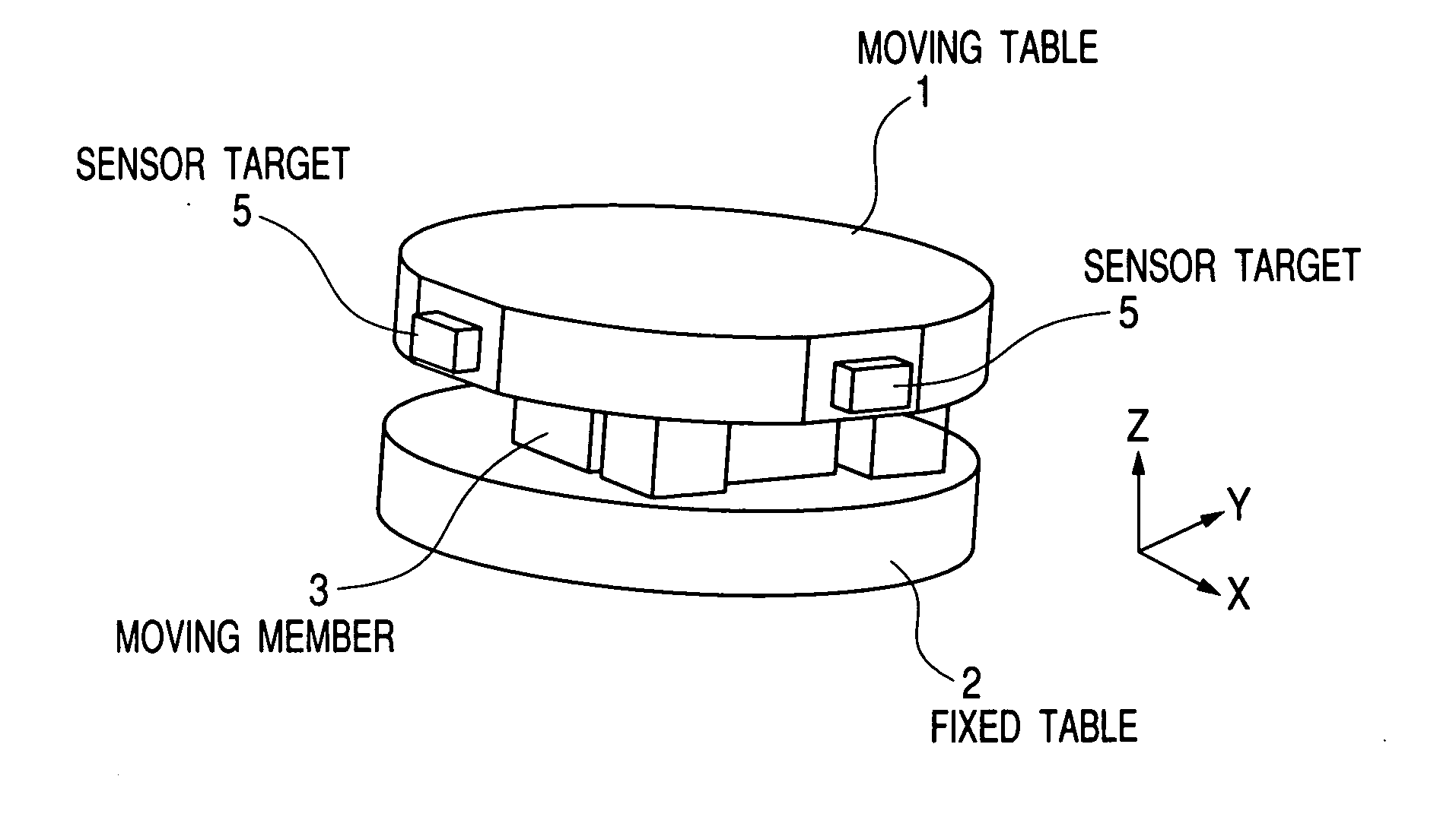
[0069] FIGS. 1 and 5 are schematic illustrations of the present invention. FIG. 5 shows an example of an exposure apparatus, in which an illumination optical system guiding light from a light source to a mask (reticle), a mask stage supporting and driving the mask, and the like are not shown, but only a projection optical system guiding light from the mask to a wafer (exposed body) and a structure supporting the projection optical system are shown. Furthermore, FIG. 1 is a perspective view of only an enlarged micro adjustment mechanism shown in FIG. 5.
[0070] An optical element six-axis micro adjustment mechanism 29 of the present invention is installed in a body tube 25 on a structure frame 2 supported on a mount 23. FIG. 5 shows an example in which total four micro adjustment mechanisms 29 are placed in the body tube 25. Of course, if the number of optical elements varies, the number of micro adjustment mechanisms should be changed according to the number of optical elements. For e...
second example
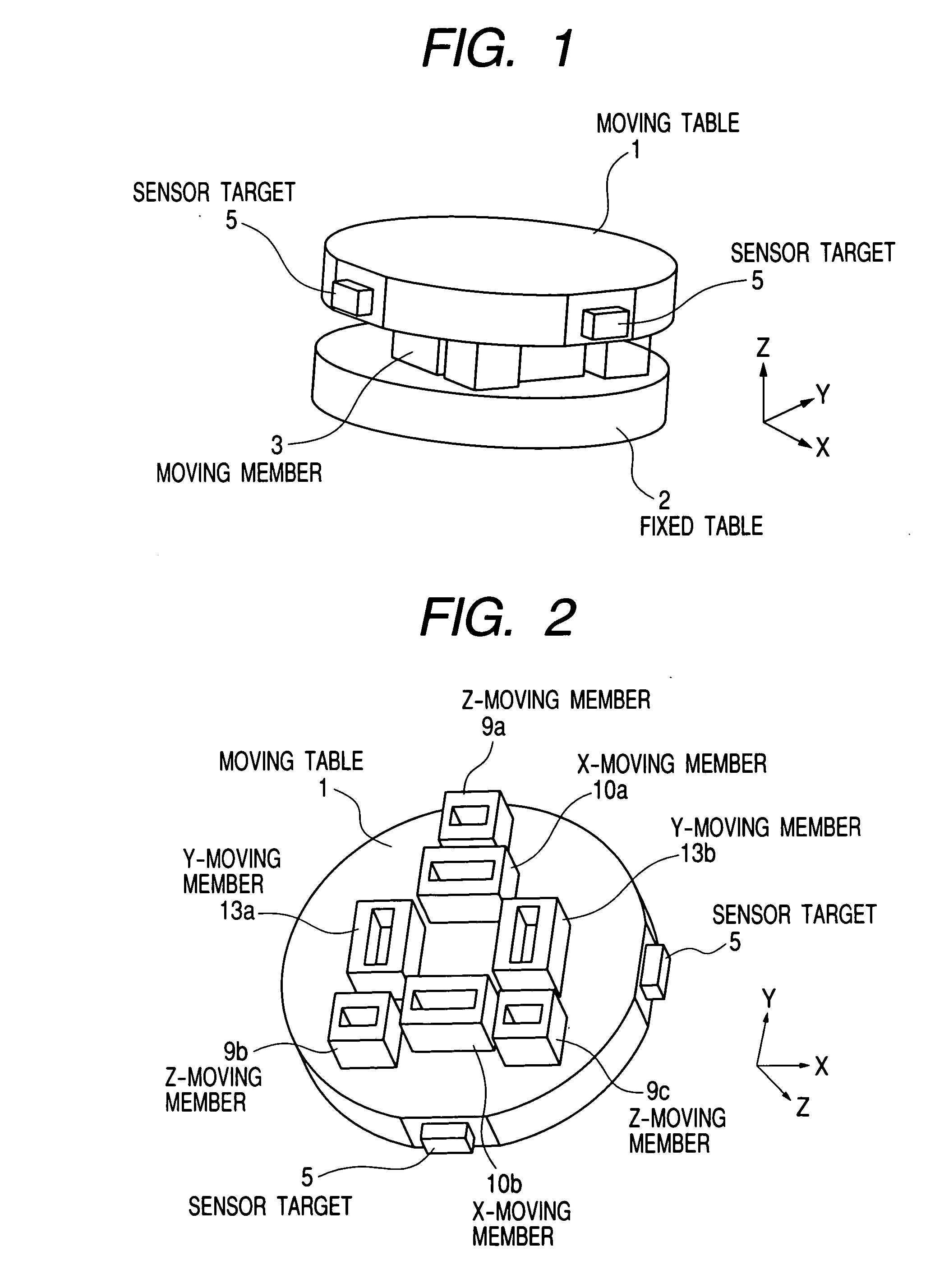
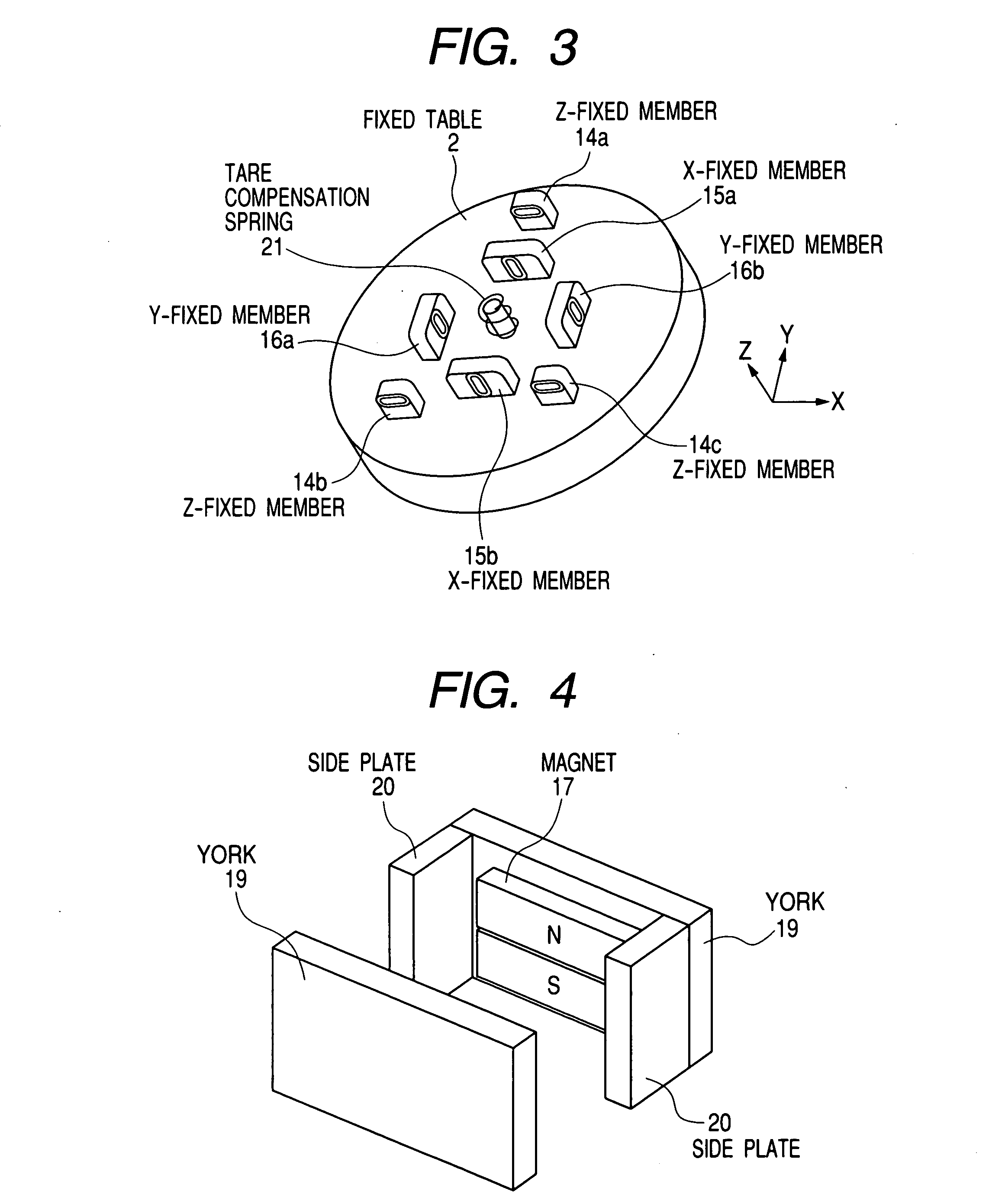
[0099] FIGS. 7 and 5 are schematic illustrations of the second embodiment of the present invention. This Example is an embodiment of realizing the linear motor with a suction force or repulsive force of an electromagnet, and the details thereof will be described below focusing on the example with the suction force of the electromagnet. This allows a moving table 1 to move in directions of six axes with respect to a fixed table 2 in a noncontact manner. Here, the directions of six axes refer to X, Y and Z directions and directions of rotation about X, Y and Z axes.
[0100] The moving table 1 is a mirror or lens being an optical element 32. Alternatively, the moving table 1 may include a holding member or the like for supporting the mirror or lens.
[0101] An actuator is a driving mechanism for driving the moving table 1 with respect to the fixed table 2. Here, the actuator has X actuators for driving the moving table 1 in the X direction, Y actuators for driving the moving table 1 in the...
third example
[0120] The exposure apparatus and the optical element positioning apparatus of the present invention will be described using FIG. 16.
[0121] The exposure apparatus shown in FIG. 16 comprises an illumination optical system 52 guiding light from a light source 53 emitting EUV light (wavelength of 10 to 15 nm) to an original plate to uniformly illuminate the original plate, a reticle stage 51 holding the original plate (mask or reticle, etc.) illuminated by the illumination optical system, a projection optical system 55 guiding light from the original plate to a substrate, a wafer stage 27 holding the substrate (wafer, etc.), and the like.
[0122] Furthermore, this exposure apparatus has a basic structure 41, and the reticle stage 51 is controlled to be positioned in directions of six axes with respect to the basic structure 41. The directions of six axes here refer to (translational directions of) directions of X, Y and Z axes, and directions of rotation about X, Y and Z axes.
[0123] The ...
PUM
 Abstract
Description
Claims
Application Information
 - Generate Ideas
- Intellectual Property
- Life Sciences
- Materials
- Tech Scout
- Unparalleled Data Quality
- Higher Quality Content
- 60% Fewer Hallucinations
Browse by: Latest US Patents, China's latest patents, Technical Efficacy Thesaurus, Application Domain, Technology Topic, Popular Technical Reports.
© 2025 PatSnap. All rights reserved.Legal|Privacy policy|Modern Slavery Act Transparency Statement|Sitemap|About US| Contact US: help@patsnap.com