
Fuse element with a temporary quasi-hermetic seal of its interior

a fuse element and quasi-hermetic seal technology, which is applied in the direction of basic electric elements, electric devices, emergency protective devices, etc., can solve the problems of affecting the operation of the fuse element, and causing the element to be damaged

Active Publication Date: 2004-09-23
WICKMANN WERKE
View PDF7 Cites 23 Cited by
  • Summary
  • Abstract
  • Description
  • Claims
  • Application Information

AI Technical Summary

Benefits of technology

[0007] This object is solved by a fuse element with the features of claim 1. Starting from a fuse element of the type referred to above, at least one respective elastic sealing element is inserted at both ends of the tube into a space between the respective cap base and the end face of the tube and / or into a portion of the cavity of the tube adjacent to the end face such that one or more pressure balancing passages remain between the gas filled cavity of the tube and the external surroundings of the fuse element of such small cross-sectional area that changes in pressure in the cavity are balanced only very slowly so that a sudden rise in pressure in the cavity, as occurs as a result of an arc, can act to quench the arc. In the event of sudden increases in pressure within a short period of time, the fuse element behaves transiently (temporarily) as though the cavity were hermetically sealed. This is referred to in the context of this description as a temporary quasi-hermetic seal of the cavity. The effective cross-sectional area and the length of the pressure balancing passage(s) between the cavity and the external surroundings should be dimensioned in dependence on the volume of the cavity and the temperature gradients occurring during installation so that a predetermined maximum pressure increase in the cavity is not exceeded during installation. This results in minimum cross-sectional areas and maximum lengths of the pressure balancing passages. On the other hand, the pressure balancing passages should be small enough so that the desired sudden pressure increase in the event of cutting out decays so slowly that it can firstly act on the arc to quench it.

Problems solved by technology

In the case of a fuse element with a hermetically sealed cavity and an air or gas filling, the energy supplied by the arc results in a sudden, violent increase of the gas pressure in the interior of the fuse element.
Disadvantageous, however, with a fuse element with a hermetically sealed interior is that the pressure increase in the interior is also produced if the fuse element is heated from the exterior, for instance during an installation process.
The pressure increase in the interior of the tube associated with such heating results in undesired stressing of the fuse element and can result in damage of the element under extreme installation conditions.

Method used


Image

  • Fuse element with a temporary quasi-hermetic seal of its interior
  • Fuse element with a temporary quasi-hermetic seal of its interior
  • Fuse element with a temporary quasi-hermetic seal of its interior

Examples


Embodiment Construction

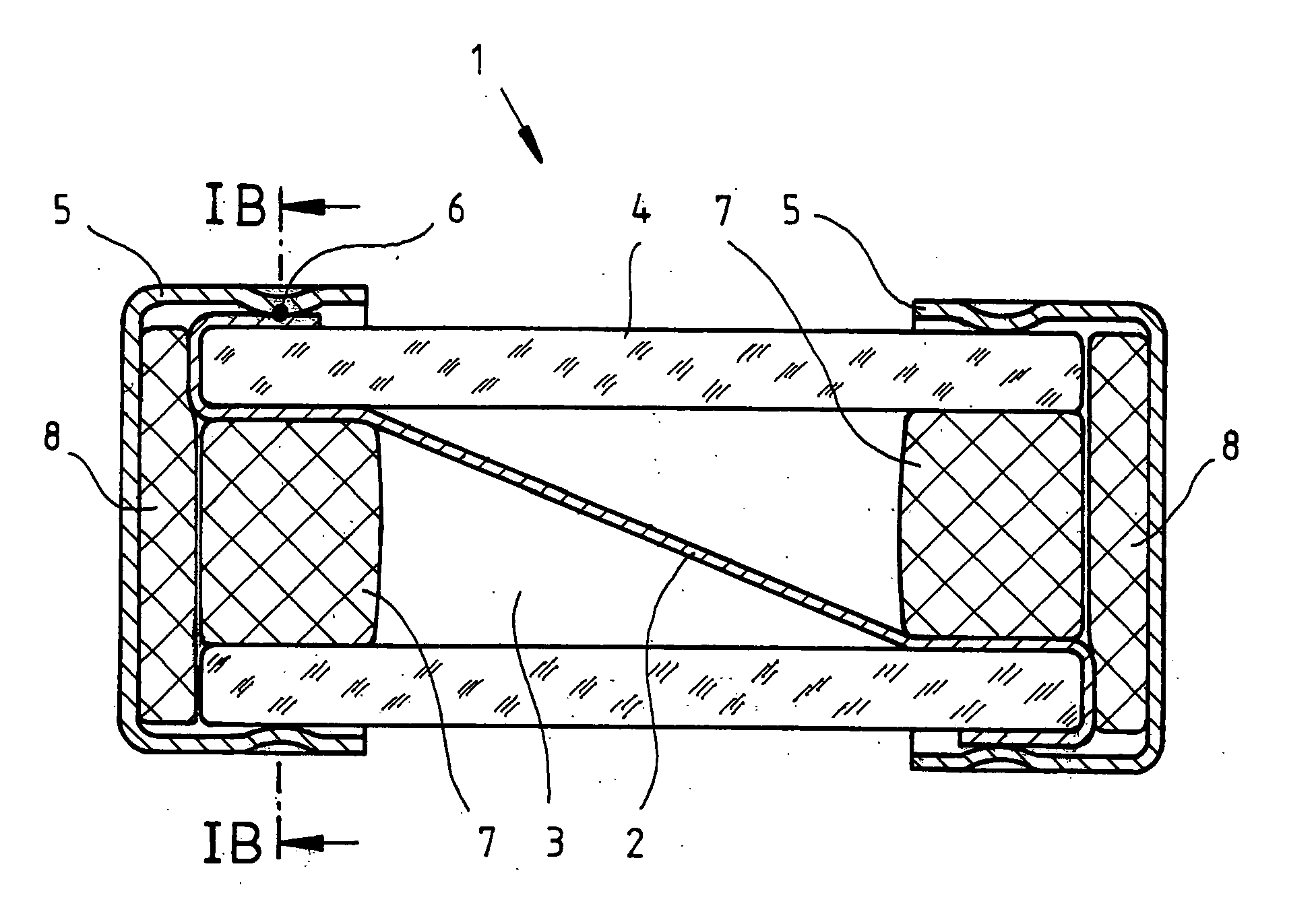
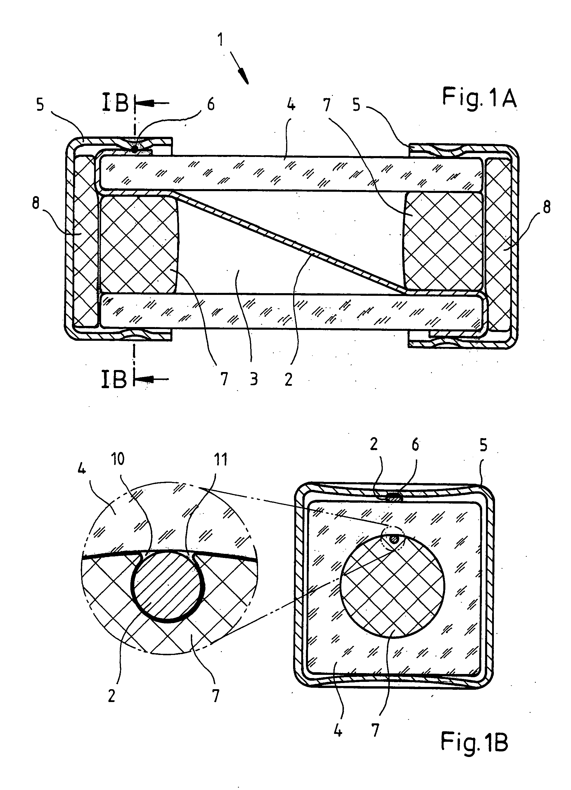
[0016] The preferred embodiment of the fuse element in accordance with the invention is illustrated in FIGS. 1A and 1B. The fuse element 1 has a fusible conductor 2, which is arranged in the internal cavity 3 of a cylindrical tube 4 such that it transverses the cavity 3 approximately diagonally. The diagonal arrangement of the fusible conductor 2 in the cavity 3 creates defined environmental conditions at the surface of the fusible conductor since it does not contact the internal walls of the tube 4. The fusible conductor 2 is, for instance, a wire with a circular cross-section. In alternative embodiments, the fusible conductor can also have a wire wound spirally around an electrically insulating core. The fusible conductor 2 can also consist of a plurality of wire sections conducted together. At the ends of the tube 4, the fusible conductor is passed around the end faces such that the ends of the fusible conductor 2 rest against the outer wall of the tube 4.

[0017] Applied to the en...


PUM


Abstract

A fuse element includes a fusible conductor which extends within a gas filled cavity in a cylindrical tube. The fuse element includes a cylindrical tube comprising, an electrical insulator between two end faces of the tube, two end caps of an electrically conductive material being applied to the two ends of the tube such that an electrical contact is produced with the fusible conductor. At least one respective sealing element is inserted in at least one of the two ends in a space between the cap base and the end face of the tube and / or into a portion of the cavity of the tube adjacent to the end face such that one or more pressure balancing passages remain between the gas filled cavity within the tube and the external surroundings of the fuse element. The one or more pressure balancing passages are of such small cross-section that changes in pressure in the cavity are balanced only very slowly. A sudden increase in pressure in the cavity, such as occurs as a result of an arc, which is produced when the fusible conductor ruptures, can act to quench the arc.

Description

1. FIELD OF THE INVENTION[0001] The invention relates to a fuse element with a fusible conductor, which extends in a cavity within a cylindrical tube comprising an electrical insulator between two end faces of the tube, two end caps of an electrically conductive material being applied to the two ends of the tube so than an electrical contact is produced with the fusible conductor.2. DESCRIPTION OF THE PRIOR ART[0002] Fuse elements of the type referred to above have been known for a long time. There are, for instance, fuse elements, in which the cylindrical tube consists of a ceramic material and has a circular cylindrical cavity and a rectangular outer shape with rounded edges. The fusible conductor is, for instance, a wire which extends diagonally within the cavity such that it contacts the walls of the tube only at the ends. The wire of the fusible conductor is passed at both ends around the end faces of the tube, whereby the ends of the fusible conductor wire engage the outer wal...

Claims


Application Information

Patent Timeline
Patent Type & Authority Applications(United States)
IPC IPC(8): H01H85/045H01H85/041H01H85/08H01H85/143H01H85/157H01H85/175
CPCH01H85/157H01H85/0418
Inventor JOLLENBECK, ANDRERODER, UWEBAUS, ANDREASALTHOFF, FRANKBARZ, WERNERPOSSNICKER, PETER
Owner WICKMANN WERKE
Features
  • Generate Ideas
  • Intellectual Property
  • Life Sciences
  • Materials
  • Tech Scout
  • Unparalleled Data Quality
  • Higher Quality Content
  • 60% Fewer Hallucinations
Learn More