Beam reconfiguration method and apparatus for satellite antennas

a satellite antenna and beam technology, applied in the direction of antenna details, antenna adaptation in movable bodies, antennas, etc., can solve the problems of inability to adapt to changing service requirements, inherently high sidelobes, and inability to provide any flexibility in coverage patterns. , to achieve the effect of increasing complexity and cost, and increasing flexibility

Inactive Publication Date: 2004-09-30
THE BOEING CO
View PDF4 Cites 55 Cited by
  • Summary
  • Abstract
  • Description
  • Claims
  • Application Information

AI Technical Summary

Benefits of technology

0058] When compared to the embodiment shown in FIG. 2, this feed array network can achieve more flexibility in terms of beam size reconfiguration, but this improvement comes at the expense of increased complexity and cost.

Problems solved by technology

Many existing satellite designs have fixed beam coverages and therefore can not provide any flexibility in terms of coverage patterns on ground and also can not be adapted to changing service requirements once the satellite has been launched.
These are risky due to the high power going through the feed, long and glossy cabling requirement, or very expensive hardware with increased power consumption on satellite.
They employ a symmetrical Cassegrain reflector antenna with main and sub-reflectors which inherently has high sidelobes and low beam efficiency due to blockage effects caused by the feed and the sub-reflector.
This method has limited beam shape reconfiguration due to the fact that the main beam splits or bifurcates for beam aspect ratios greater than 1:2.5 and therefore resulting in poor gain performance.
This scheme provides limited reconfigurability over a narrow bandwidth and employs complicated and expensive hardware.
This requires feed movement and also reflector movement (main or sub-reflector) and also has limited range of beam size reconfiguration (beam size aspect ratio of less than 1:2) due to the use of single feed and has disadvantages associated with feed movement.
This is mainly intended for fixed beam applications and does not provide the beam size flexibility.

Method used


Image

  • Beam reconfiguration method and apparatus for satellite antennas
  • Beam reconfiguration method and apparatus for satellite antennas
  • Beam reconfiguration method and apparatus for satellite antennas

Examples


Embodiment Construction

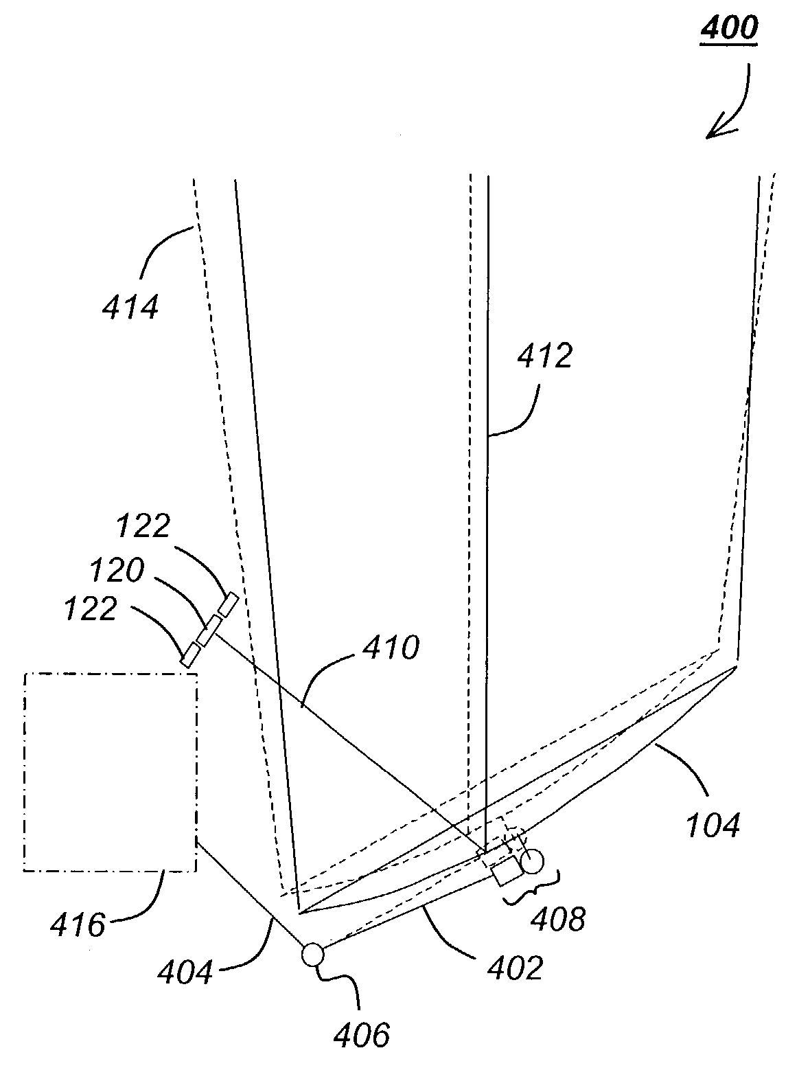
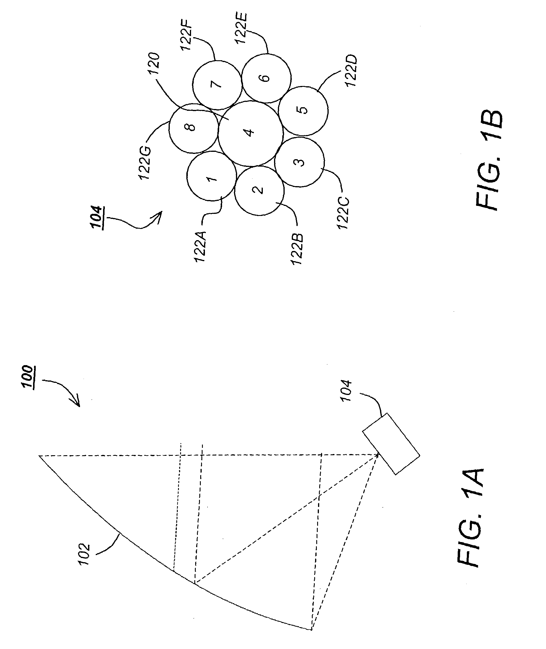
[0035] FIG. 1A is a diagram of one embodiment of the reconfigurable antenna system 100. It uses a large deployable offset reflector 102 being fed with an 8 element feed array 104. The reflector has a 252 inch diameter projected aperture, a focal length of 160 inches, and an offset clearance of 50 inches in order to avoid the feed array 104 blockage. In the illustrated embodiment, the reflector 102 shape is parabolic but can be other shapes as well, to suit the particular application.

[0036] FIG. 1B is a diagram depicting one embodiment of the feed array 104. The feed array 104 includes a primary element 120 and a plurality of secondary elements 122A-122G disposed about the periphery of and surrounding the primary element 120. In one embodiment, the primary element 120 includes a first cup-dipole and the secondary elements include seven or more second cup-dipoles smaller in diameter than the first cup dipole (e.g. 13.0 and 10.0 inches in diameter, respectively).

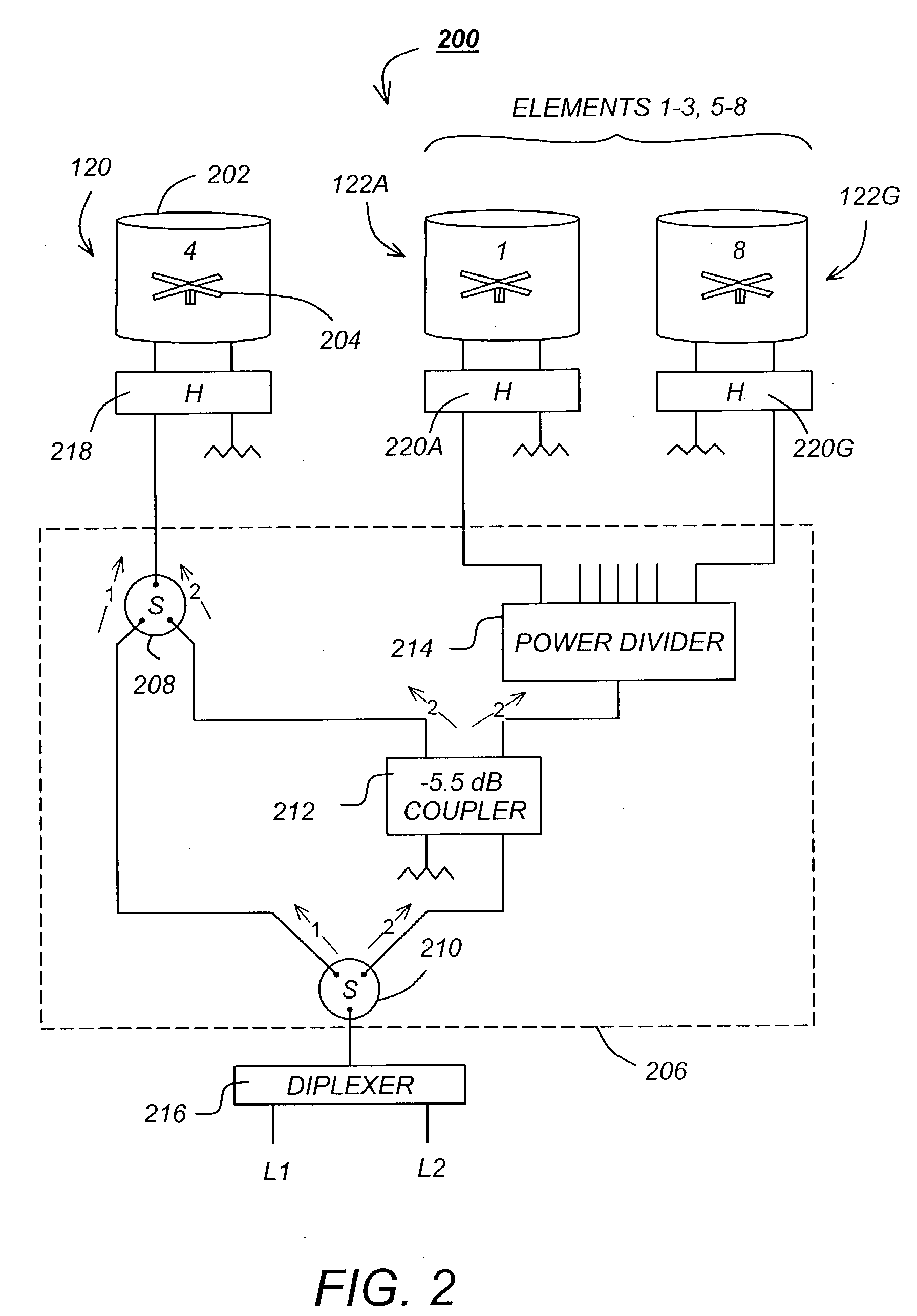
[0037] FIG. 2 is a sche...


PUM


Abstract

A method, apparatus, article of manufacture, and a memory structure for generating reconfigurable beams is disclosed herein. The apparatus comprises a stationary feed array having a plurality of selectably activatable feed array elements, the feed array having a feed array sensitive axis; a reflector, illuminated by the selectably activatable feed array elements; a first mechanism, coupled to the reflector, for varying a position of the reflector along the feed array axis; wherein a desired beam size of the antenna system is selected by varying the reflector position along the feed array sensitive axis and by selectably activating the feed array elements.

Description

[0001] 1. Field of the Invention[0002] The present invention relates to systems and methods for transmitting / receiving data, and in particular to a system and method for on-orbit reconfiguration of beams transmitted / received by satellite antennas.[0003] 2. Description of the Related Art[0004] Commercial and military satellites often require the flexibility in terms of changing the coverage size and the beam location over the global field-of-view. It is also important to keep the feed(s) stationary for most applications either due to the high power required to carry multiple frequency channels on-board the satellite or to avoid long cables required to move the feed(s).[0005] Many existing satellite designs have fixed beam coverages and therefore can not provide any flexibility in terms of coverage patterns on ground and also can not be adapted to changing service requirements once the satellite has been launched.[0006] Future applications for both commercial and military satellites m...

Claims


Application Information

Patent Timeline
Patent Type & Authority Applications(United States)
IPC IPC(8): H01Q1/28H01Q3/20H01Q3/24H01Q19/13H01Q25/00
CPCH01Q1/288H01Q3/20Y10S343/02H01Q19/132H01Q25/007H01Q3/245
Inventor RAO, SUDHAKAR K.GOYETTE, GUYMASSEY, CAMERONVOULELIKAS, GEORGEFINK, JOEL A.
Owner THE BOEING CO
Why Eureka
Try Eureka