Tape printing apparatus with tape cassette guide members

a technology of tape printing and guide members, which is applied in printing, typewriters, inking apparatuses, etc., can solve the problems of tape jamming, tape catching in the parts arranged around the thermal head holding member, and unusability of tape cassettes

Active Publication Date: 2004-09-30
BROTHER KOGYO KK
View PDF22 Cites 9 Cited by
  • Summary
  • Abstract
  • Description
  • Claims
  • Application Information

AI Technical Summary

Problems solved by technology

Therefore, when the tape is drawn out from a release part of the tape cassette, there is a danger of the tape catching in the parts arranged around the thermal head holding member.
Sometimes, the naked part of the tape is caught in the FFT or another part arranged around the t

Method used


Image

  • Tape printing apparatus with tape cassette guide members
  • Tape printing apparatus with tape cassette guide members
  • Tape printing apparatus with tape cassette guide members

Examples


Embodiment Construction

[0031] Exemplary embodiments of the invention will be described below in detail with reference to the accompanying drawings.

[0032] A first exemplary embodiment of the invention will be described by reference to FIG. 1 through FIG. 4.

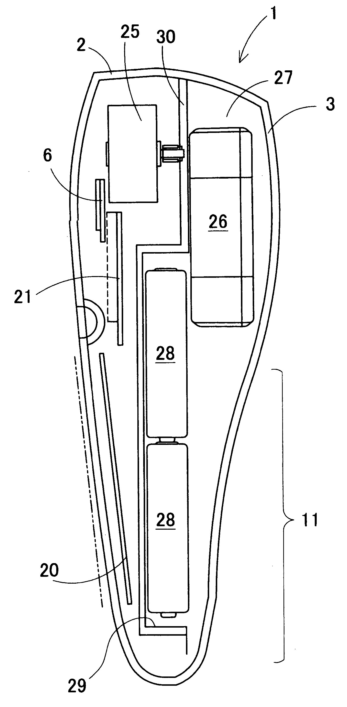
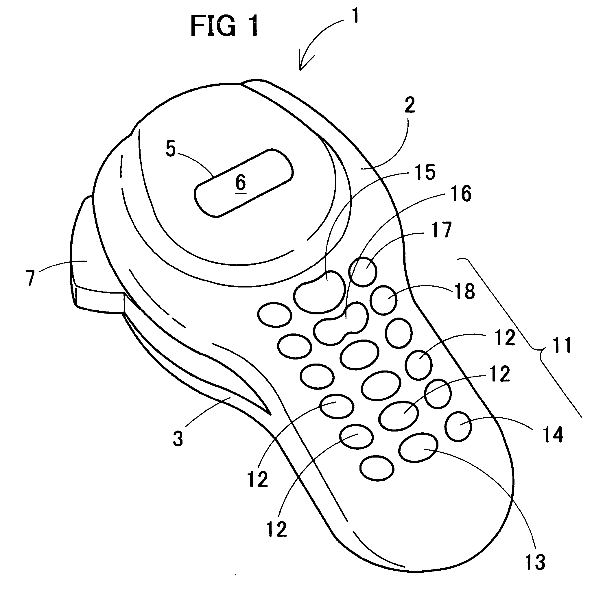
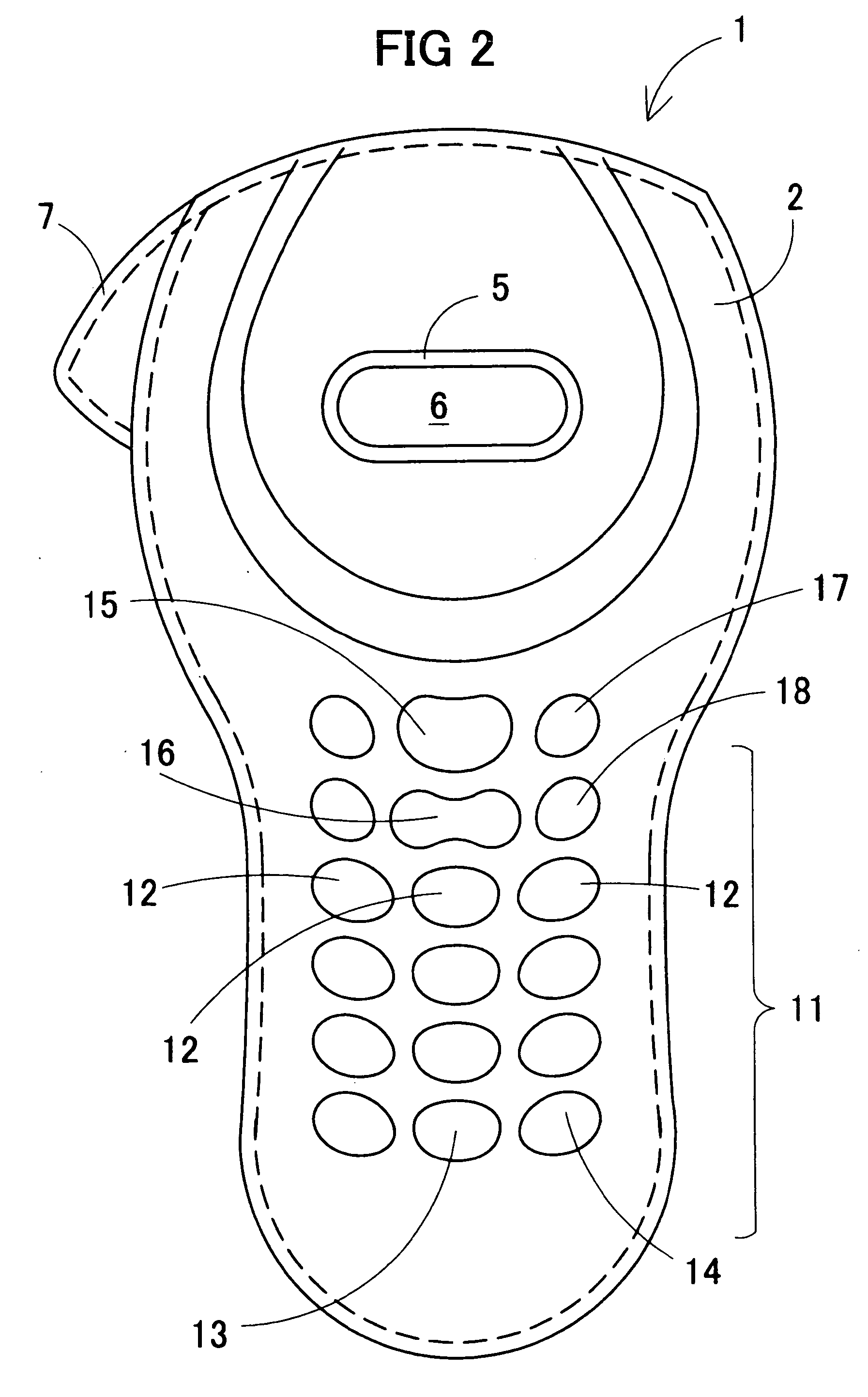
[0033] As shown in FIG. 1 through FIG. 4, the tape printing apparatus 1 includes a body 2 (in this example, made from plastic), and a detachable rear cover 3 (in this example, made from plastic) which covers the whole rear side of the body 2, the opposite side of the side facing a user when the user uses the tape printing apparatus. The upper part of the body 2 in a longitudinal direction may be formed in a substantially rounded shape. The body 2 has an oblong window 5 provided substantially in the center of the surface of the upper part. A display 6 is arranged under this window 5. The display may be any suitable display, such as, e.g., an LCD (liquid crystal display).

[0034] A cut lever 7 is provided in the left side part of the display 6. A tape (not s...


PUM


Abstract

A tape printing apparatus uses a tape cassette having two guide holes, the tape printing apparatus has a tape cassette holder including at least first and second guide members; the first guide member having a height that is shorter than a height of the second guide member; such that the second guide member is inserted into a second guide hole on the tape cassette before the first guide member is inserted into a first guide hole of the tape cassette.

Description

[0001] 1. Field of Invention[0002] This invention relates to a tape printing apparatus using a thermal head for printing characters or other images on a tape. This invention particularly relates to a tape printing apparatus that allows any user to install the tape cassette easily and without tape jam.[0003] 2. Description of Related Art[0004] Various related art tape printers have been proposed which use a thermal head to print characters and the like on a tape stored in a tape cassette and installed in a tape cassette holder. See, e.g., Japanese Patent Application Laid-Open No. HEI8-025753.[0005] These compact tape printing apparatus generally use tape cassettes which store tape and ink ribbon. The tape cassette is attached to the tape cassette holder on the tape printing apparatus. The thermal head is provided on a thermal head holding member. The thermal head holding member projects into the tape cassette holder. The tape and ribbon for printing are stored in the tape cassette.[0...

Claims


Application Information

Patent Timeline
IPC IPC(8): B41J3/407B41J3/36B41J11/00B41J15/02B41J15/04
CPCB41J15/044B41J3/4075
Inventor TANAKA, MITSUGI
Owner BROTHER KOGYO KK
Why Eureka
Try Eureka