Wireless bar code symbol driven portable data terminal ( PDT) system adapted for single handed operation

a portable data terminal and bar code technology, applied in the field of wireless bar code driven portable data terminals, can solve the problems of affecting the overall end-user experience, difficult to operate this kind of pdt in a truly single-handed operation, and affecting the user experience, so as to achieve easy and controllable single-handed operation

Inactive Publication Date: 2004-10-21
METROLOGIC INSTR
View PDF99 Cites 72 Cited by
  • Summary
  • Abstract
  • Description
  • Claims
  • Application Information

AI Technical Summary

Benefits of technology

[0013] Thus, there is a great need in the art for an improved wireless bar code driven PDT system, improved methods of data capture and transaction processing, and improved development and deployment environments therefor, while overcoming the above described shortcomings and drawbacks of prior art systems and methodologies.

Problems solved by technology

While this prior art PDT design has been used for years in various applications, it suffers from a number of shortcomings and drawbacks which detract from the overall end-user experience.
In particular, due to the overall physical configuration of this prior art PDT design, it is very difficult to operate this kind of PDT in a truly single-handed operation.
By requiring two handed operation, the user experience is typically compromised in ways which can reduce worker productivity and efficiency.
For example, the operator cannot easily hold a bar coded garment in one hand while manually keying product-related data into the PDT being held in his or her other hand.
Also, backlit LCD-type display screens provided on such prior art PDTs are generally difficult to view in brightly lit user environments.
Another problem with such prior art PDT designs is that they do not enable simple navigation of the display screen cursor while attempting the operate the PDT using only one hand of the operator.
Another problem with such prior art PDT designs is that they do not typically support development of powerful end-user applications in a simple low cost manner, nor do they enable easy and flexible deployment of developed applications in portable run-time environments that are supported by open-source operating systems having no or low user license fees associated therewith.

Method used


Image

  • Wireless bar code symbol driven portable data terminal ( PDT) system adapted for single handed operation
  • Wireless bar code symbol driven portable data terminal ( PDT) system adapted for single handed operation
  • Wireless bar code symbol driven portable data terminal ( PDT) system adapted for single handed operation

Examples


Embodiment Construction

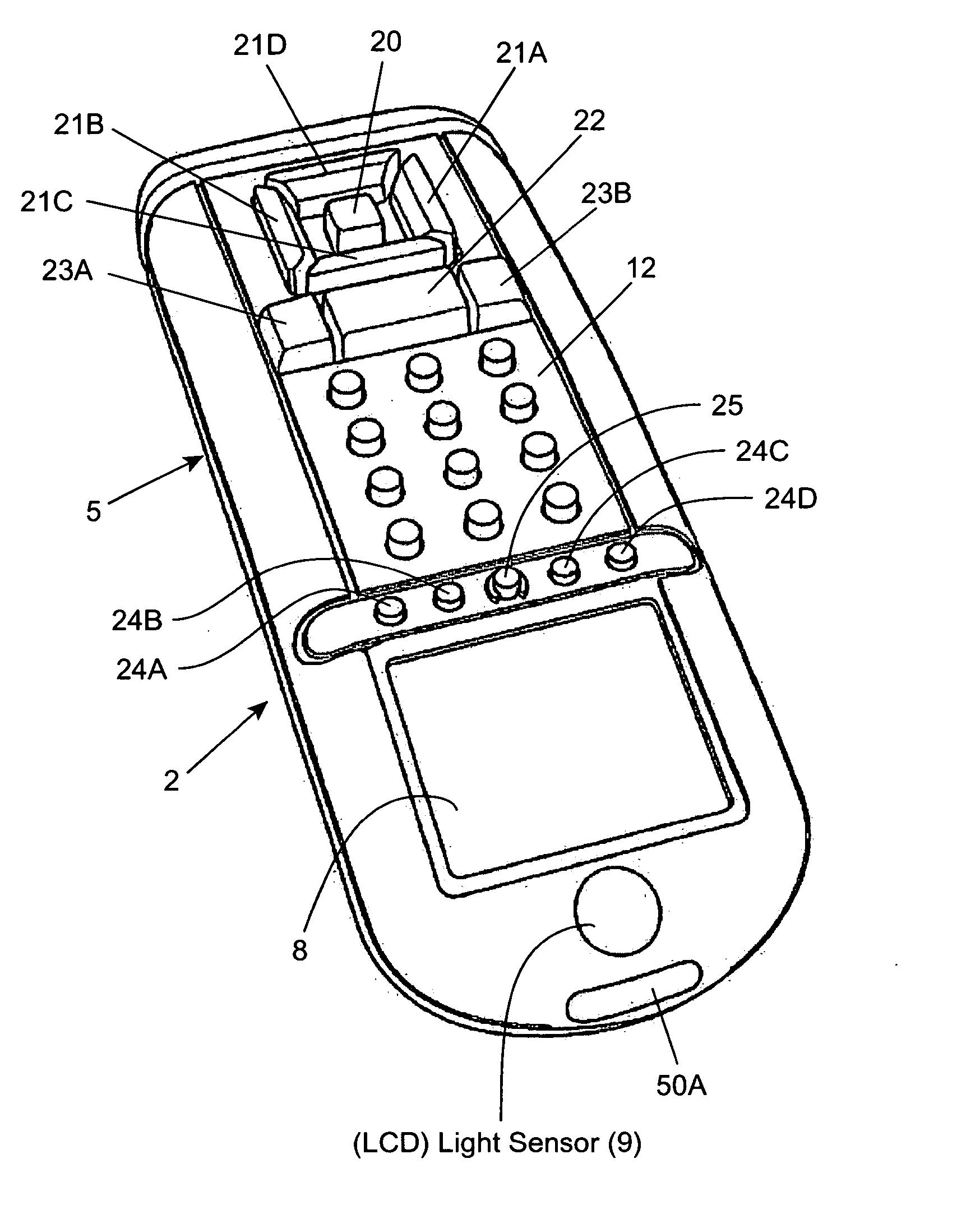
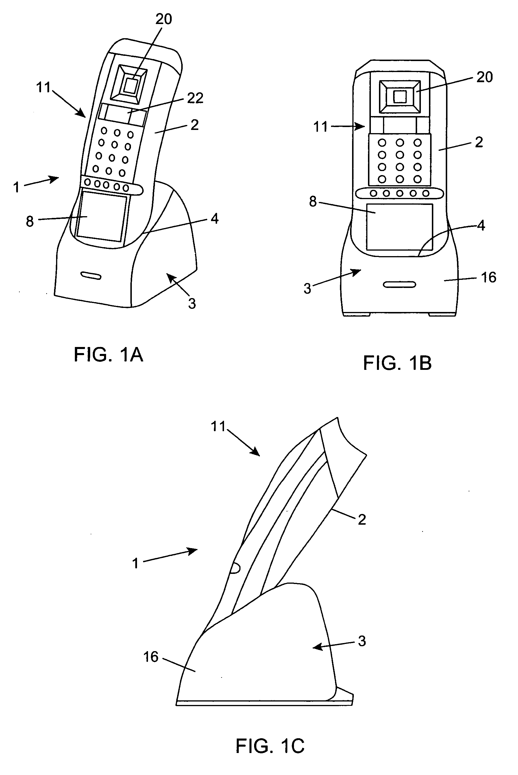
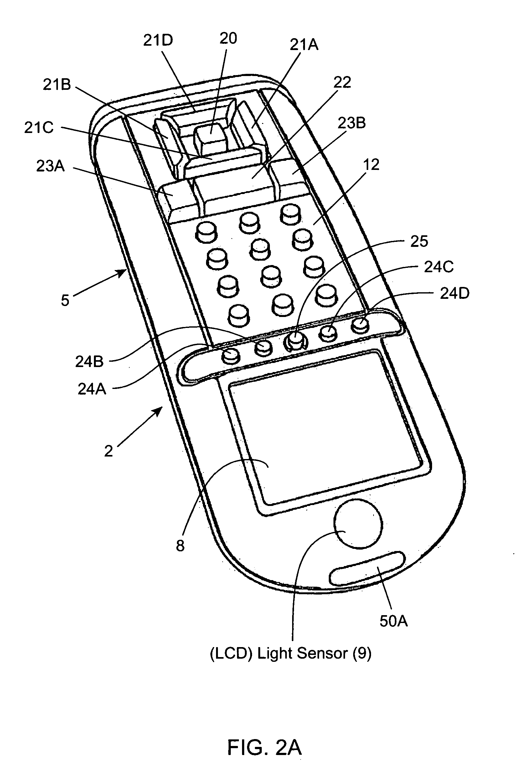
[0095] Referring to the figures in the accompanying Drawings, the various illustrative embodiments of the automatically-activated laser scanning bar code symbol reading system of the present invention will be described in great detail, wherein like elements will be indicated using like reference numerals.

[0096] In general, the present invention has several different aspects which can be best appreciated when viewed as a single exposition.

[0097] The first aspect of the present invention relates to a novel wireless bar code symbol driven portable data terminal (PDT) system physically configured for truly single-handed operation.

[0098] The second aspect of invention relates to a novel method of navigating through and interacting with information structures within database using the wireless PDT of the present invention.

[0099] The third aspect of the present invention relates to a novel integrated development environment that supports rapid visual-based development of end-user applicati...


PUM


Abstract

A wireless PDT of the present invention employing a "display-on bottom" design which places the unit perfectly centered in the hand of the operator, allowing for the best possible viewing as well as providing comfortable single-handed operation. The high-resolution LCD display allows the PCT to show sharp, clear bitmap images while supporting all Windows-recognized font types and sizes. With the auto back-lit feature, the brightness adjusts automatically making the screen easy to read in all light conditions. The PDT is designed for support within the download / charger cradle of a base station which interfaces with a host system using either USB or RS232 interface. Two standard 'AA' or rechargeable Li-Ion batteries provide more than 100 hours of operation. In addition, the PDT comes standard with 2 MB of RAM providing enough memory to store over 100,000 records.

Description

RELATED CASES[0001] The present application is a continuation-in-part (CIP) of: pending U.S. application Ser. No. 09 / 960,247 filed Sep. 21, 2001; pending U.S. application Ser. No. 09 / 990,585 filed Nov. 21, 2001; pending U.S. application Ser. No. ______ (no serial number assigned yet) entitled "Automatically-Activated Hand-Supportable Multi-Mode Laser Scanning Bar Code Symbol Reading System" filed Nov. 13, 2002; pending U.S. application Ser. No. 09 / 999,687 filed Oct. 31, 2001; pending U.S. application Ser. No. 09 / 954,477 filed Sep. 17, 2001; Ser. No. 09 / 883,130 filed Jun. 15, 2001; pending U.S. application Ser. No. 09 / 781,665 filed Feb. 12, 2001; pending U.S. application Ser. No. 09 / 780,027 filed Feb. 9, 2001; pending U.S. application Ser. No. 09 / 721,885 filed Nov. 24, 2000; pending U.S. application Ser. No. 09 / 047,146 filed Mar. 24, 1998; pending U.S. application Ser. No. 09 / 157,778 filed Sep. 21, 1998; pending U.S. application Ser. No. 09 / 274,265 filed Mar. 22, 1999; U.S. applicati...

Claims


Application Information

Patent Timeline
Patent Type & Authority Applications(United States)
IPC IPC(8): G06K5/00G06K7/10G06K9/22G06K19/06H04N
CPCG06K7/10881G06K17/0022G06K7/10158
Inventor SCHMIDT, MARKRUSSELL, GARRETT K.KNOWLES, C. HARRYZHU, XIAOXUNAU, KA MANXU, CONGWEILIU, LIANGJI, KAIZHANG, WUQING
Owner METROLOGIC INSTR
Why Eureka
Try Eureka