Hydrodynamic foil face seal

Inactive Publication Date: 2004-10-21
R & D DYNAMICS
View PDF17 Cites 36 Cited by
  • Summary
  • Abstract
  • Description
  • Claims
  • Application Information

AI Technical Summary

Problems solved by technology

Where this cannot be guaranteed, such as inside a gas turbine engine, success has proved elusive.
However, it is pointed out that leakage is much lower than what can be obtained from any other potential seal type, and is still expected to provide over 1% savings in engine specific fuel consump

Method used


Image

  • Hydrodynamic foil face seal
  • Hydrodynamic foil face seal
  • Hydrodynamic foil face seal

Examples


first embodiment

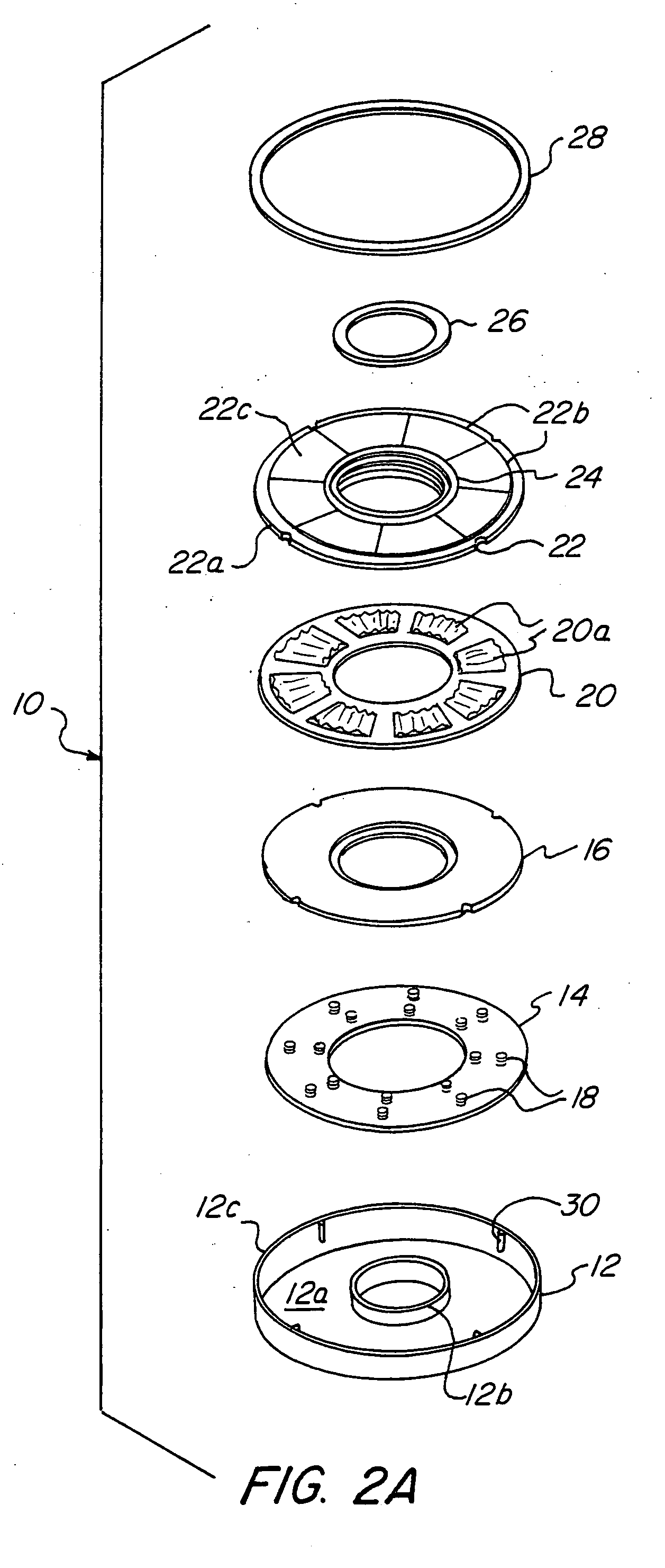
[0037] a face seal according to this invention is shown in the exploded perspective view of FIG. 2A and in the cross-sectional view of FIG. 2B. Referring now to both FIGS. 2A and 2B, seal 10 having a diameter of about 12 centimeters (cm) (4.7 inches) comprises an annular face seal case 12, a spring base plate 14, a support plate 16, springs 18, a bump plate 20, a top plate 22 and a seal ring 24. Seal 10 also comprises two retaining rings, an inner retaining ring 26 and an outer retaining ring 28.

[0038] Face seal case 12 defines a flat face 12a and two concentric flanges, including an inner flange 12b having an interior diameter of about 4.1 cm (1.6 inches) and a thickness of about 0.63 millimeters (mm) (0.025 inch) and an outer flange 12c. In the orientation shown in FIGS. 2A and 2B, outer flange 12c rises to a greater height than inner flange 12b relative to face 12a by about 2.54 mm (0.1 inch). Together, face 12a and flanges 12b and 12c define an annular channel within which the o...


PUM


Abstract

A foil thrust bearing forms the primary rotating interface for a film riding face seal. This face seal includes a spring system that will allow the entire assembly to translate axially relative to a static attachment. The complete assembly will form a hybrid foil/film riding face seal that shows much promise at being sufficiently flexible to enable operation in a gas turbine engine. The seal includes a flexible top plate having a non-flat surface under its working conditions, and a spring support system to allow the top plate to accommodate axial excursions and out-of-flat distortions.

Description

[0001] This application claims the benefit of U.S. Provisional Application Ser. No. 60 / 303,588, filed Jul. 6, 2001.[0002] 1. Field of the Invention[0003] This invention pertains to the field of gas riding face seals.[0004] Gas turbine engines bleed off some of the compressed air from the primary gas path into so-called secondary flow circuits for various reasons, mainly to cool various components within the engine. This withdrawal of air is a parasitic loss to the engine thermodynamic cycle causing degradation in efficiency.[0005] Secondary airflows are metered via air-to-air seals that are typically placed at interstage locations in the turbine engine. Relative velocities are high, typically about 150 meters / second (about 500 ft / sec) and up, and temperatures in the turbine section of the engine of about 425.degree. C. (about 800.degree. F.) and greater are typical. Since the beginning of the gas turbine, labyrinth seals have traditionally been used to seal these locations. Unfortun...

Claims


Application Information

Patent Timeline
IPC IPC(8): F16C17/12F16J15/34
CPCF16C17/042F16J15/3432F16C2360/23
Inventor AGRAWAL, GIRIDHARI L.PATEL, KIRTIKUMAR H.MUNSON, JOHN H.
Owner R & D DYNAMICS
Why Eureka
Try Eureka