Lighting unit with improved cooling

a technology of light-emitting units and cooling elements, which is applied in the direction of lighting and heating equipment, electrical equipment, etc., can solve the problems of high cost of highly thermally conductive materials, inefficient cooling of leds, and rapid luminous efficiency of leds used in such lighting units

Inactive Publication Date: 2004-10-21
PULSAR LIGHT OF CAMBRIDGE
View PDF6 Cites 56 Cited by
  • Summary
  • Abstract
  • Description
  • Claims
  • Application Information

AI Technical Summary

Problems solved by technology

It has been found that the luminous efficiency of the LEDs used in such lighting units falls rapidly if their operating temperature is permitted to exceed about 40.degree. Celsius while operating at higher currents.
However, the highly thermally conductive material is very e

Method used


Image

  • Lighting unit with improved cooling
  • Lighting unit with improved cooling
  • Lighting unit with improved cooling

Examples


Embodiment Construction

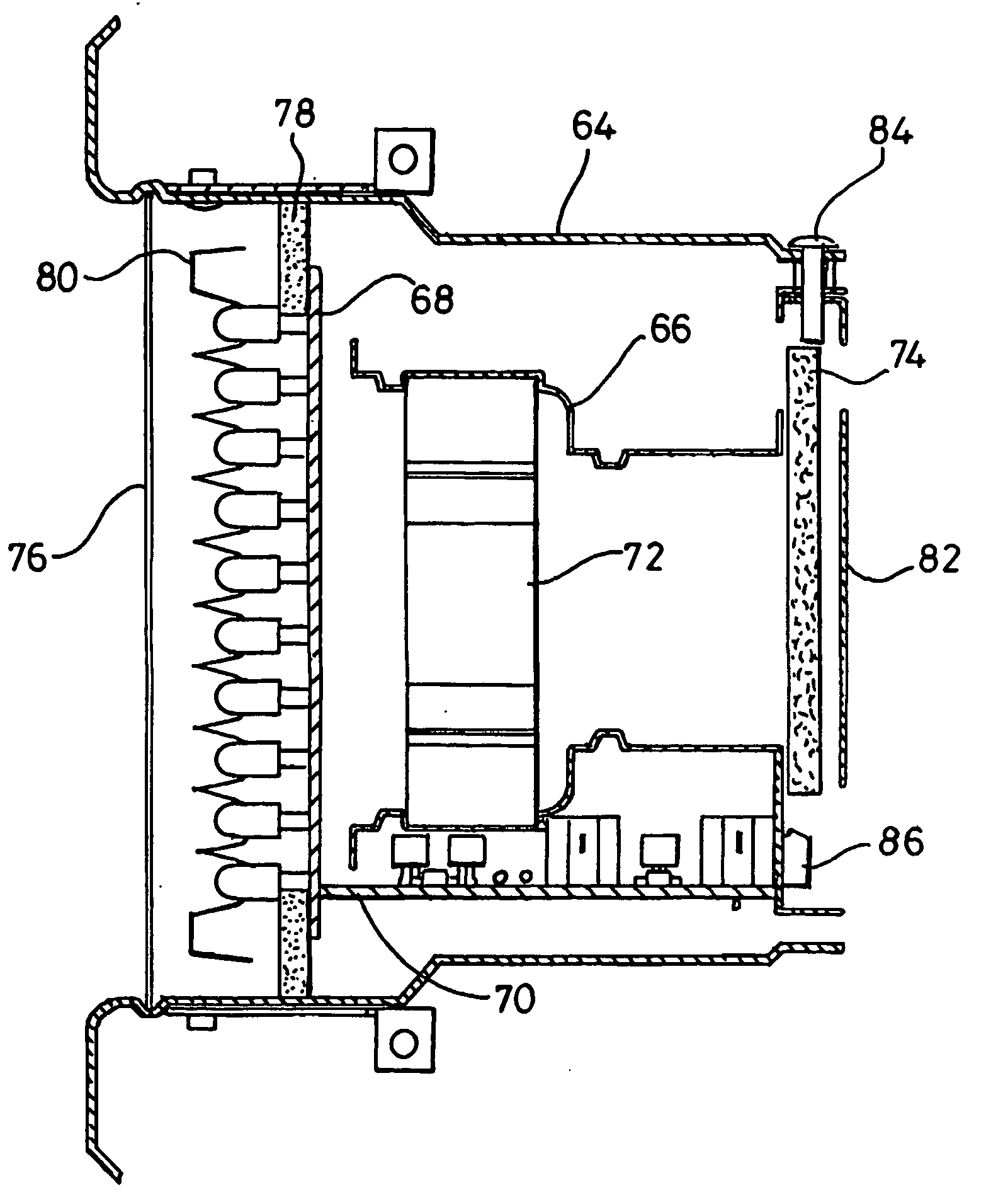
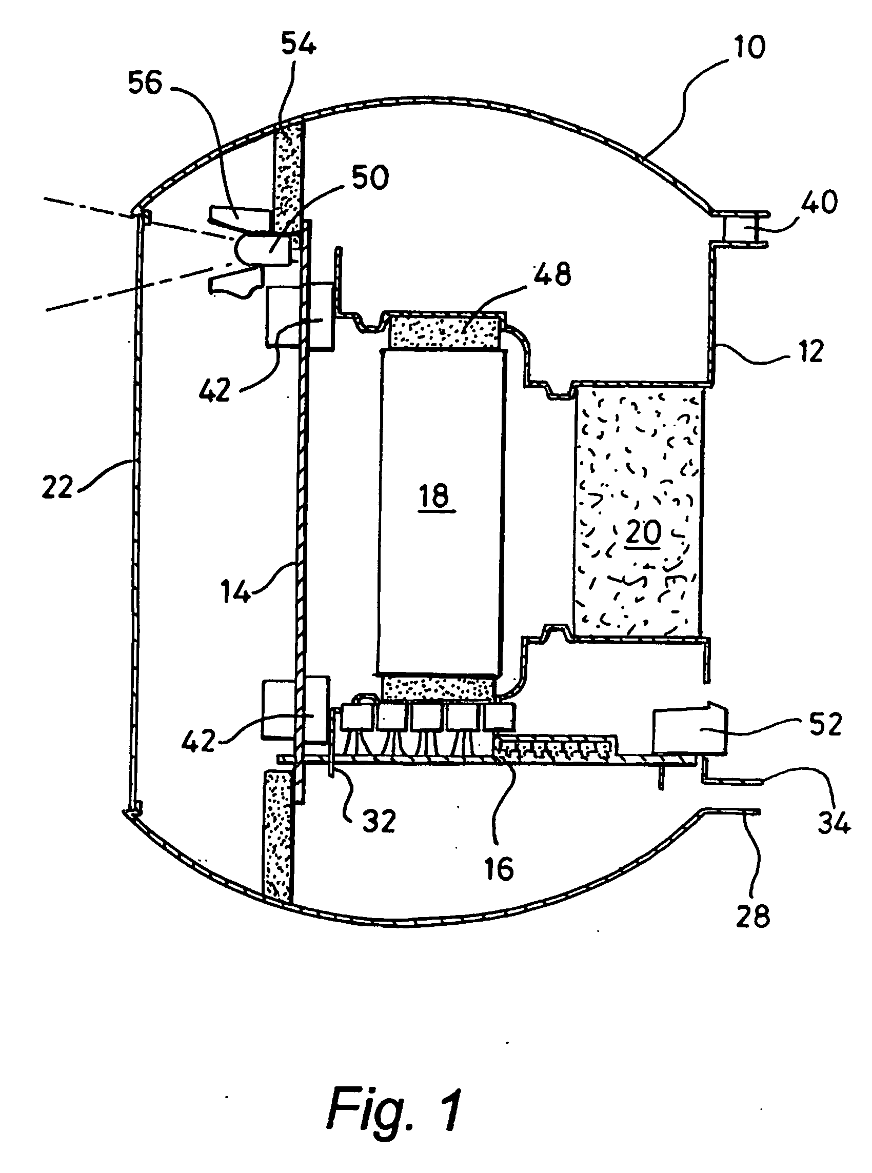
[0031] Referring to FIG. 1, a lighting unit comprises a housing 10 containing a core 12, first and second circuit boards 14 and 16 respectively, an electric fan 18, a filter 20 and a diffusing lens 22. The core 12 is fastened to the housing 10 by screws (not shown). The first and second circuit boards are joined at right angles along one edge and the first circuit board 14 is fastened to the core 12 by screws (not shown).

[0032] Referring to FIG. 2, the housing 10 is formed from aluminium and is generally tubular with convex walls and front and rear circular openings 24 and 26 respectively. The front opening 24 has an integrally formed bezel to retain the diffusing lens 22, which is moulded from polycarbonate. The rear opening 26 is formed with a tubular rim 28. The rim 28 has three screw holes 30 spaced equi-angularly around its circumference, of which two are visible in FIG. 2.

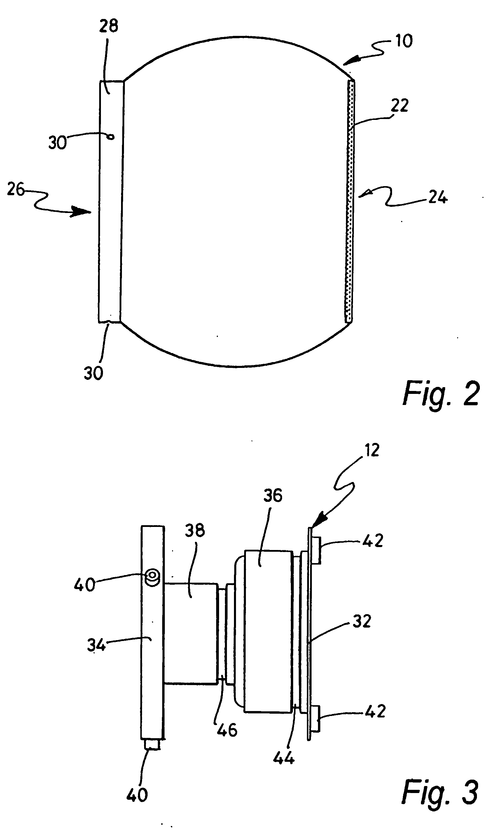
[0033] Referring to FIG. 3, the core 12 is formed from aluminium and is generally tubular with front and r...


PUM


Abstract

Disclosed is a lighting unit comprising at least one light emitting diode (50), means for supplying power to the light emitting diode (50), and a motor driven pump means (18) for generating a stream of fluid for cooling the light emitting diode (50). The pump means is mounted in a resiliently compressible member (48) for absorbing vibrations produced by the pump means (18) which reduces the level of noise produced by the lighting unit. The lighting unit has control means operable to gradually increase or decease the speed of operation of the pump means in response to the power dissipation of the light emitting diode exceeding or falling below, respectively, a threshold level, which makes the noise produced by the pump means less noticeable.

Description

[0001] This invention relates to a lighting unit, and in particular to a lighting unit comprising at least one light emitting diode.BACKGROUND TO THE INVENTION[0002] Lighting units that use a plurality of light emitting diodes (LEDs) are known. These typically comprise a plurality of each of red, green and blue LEDs, control of the relative brightness of which determines the colour of light generated by the lighting unit. It has been found that the luminous efficiency of the LEDs used in such lighting units falls rapidly if their operating temperature is permitted to exceed about 40.degree. Celsius while operating at higher currents. To date, therefore, such lighting units have employed a sheet of a highly thermally conductive material that is placed in good thermal contact with, and conducts heat away from, the LEDs. However, the highly thermally conductive material is very expensive and provides a relatively inefficient means of cooling the LEDs, which must be used at currents les...

Claims


Application Information

Patent Timeline
IPC IPC(8): F21V29/02
CPCF21K9/00F21V29/02F21V29/677F21Y2101/02H05B33/0803F21V29/30F21Y2115/10H05B45/30
Inventor MARDON, PAUL FRANCISGREGORY, MARK LEONARD
Owner PULSAR LIGHT OF CAMBRIDGE
Why Eureka
Try Eureka