
Orthodontic wire ligating member

Inactive Publication Date: 2004-10-21
DENTSPLY SANKIN KK
View PDF9 Cites 13 Cited by
  • Summary
  • Abstract
  • Description
  • Claims
  • Application Information

AI Technical Summary

Benefits of technology

[0014] Another object of the present invention is to provide an orthodontic wire ligating member that allows tooth movement in a friction-free state (i.e. a state where friction can be minimized in the present invention) or in a low-friction state, so that the desired tooth movement is effected rapidly and thus the period of time for orthodontic treatment is shortened.
[0015] Still another object of the present invention is to provide an orthodontic wire ligating member that allows tooth movement to be effected with a small corrective force, thereby minimizing pain inflicted on the patient.
[0016] A further object of the present invention is to provide an orthodontic wire ligating member having an archwire retaining structure with a minimum of unevenness and a smoothly curved external configuration to improve aesthetics.

Problems solved by technology

This inflicts pain on the patient.
With the conventional ligating methods using a metal wire, rubber, etc., the archwire is held down to the bracket slot surface with an excessive pressing force.
These unnecessary forces make it difficult to effect the desired tooth movement.
Accordingly, as the orthodontic treatment progresses, improper force other than force necessary for the movement of the patient's teeth acts.
This gives a foreign body sensation to the patient, irritates the mucous membrane of the mouth, and inflicts orthodontic pain on the patient during the treatment.
However, the bracket has a large and complicated structure because it comprises a slide member, a spring member, etc.
Further, there are cases where a special-purpose tool is needed to attach and detach the slide member or the spring member to and from the bracket.
Moreover, the foregoing conventional ligating methods are unhygienic because food and plaque are likely to be left on the orthodontic appliances.
Therefore, the conventional methods have a problem in terms of aesthetics.
However, the lingual bracket 13 has the disadvantage that it is difficult to carry out orthodontic treatment.

Method used


Image

  • Orthodontic wire ligating member
  • Orthodontic wire ligating member
  • Orthodontic wire ligating member

Examples


Embodiment Construction

s]

[0077] The operation / working-effect of the embodiments detailed above may be summarized as follows. The wire securing methods using the conventional ligating members are complicated and require the orthodontist to have highly proficient skill in ligating. In contrast, the orthodontic wire ligating member according to any of the embodiments of the present invention enables the treatment to be finished in a reduced period of time and moreover allows orthodontic pain inflicted on the patient to be reduced to a considerable extent. The bracket configuration is not restricted to the conventional ones. However, the use of an optimal bracket configuration conformable to the ligating members according to the embodiments enables the effect of the orthodontic treatment to be improved furthermore.

[0078] Existing conventional devices capable of manifesting an effective corrective force when used for tooth movement are designed on the assumption that an archwire, an elastic chain, a coil sprin...


PUM


Abstract

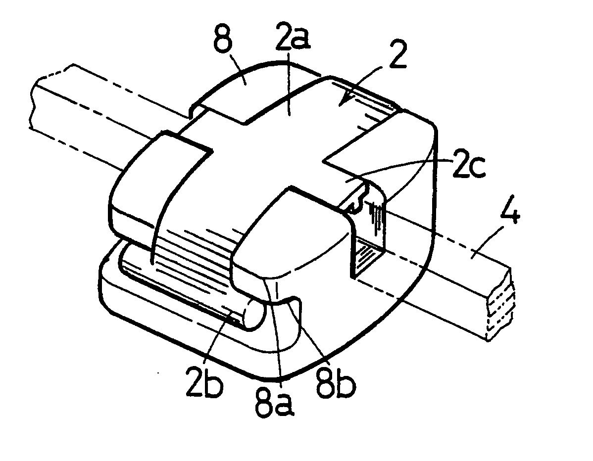
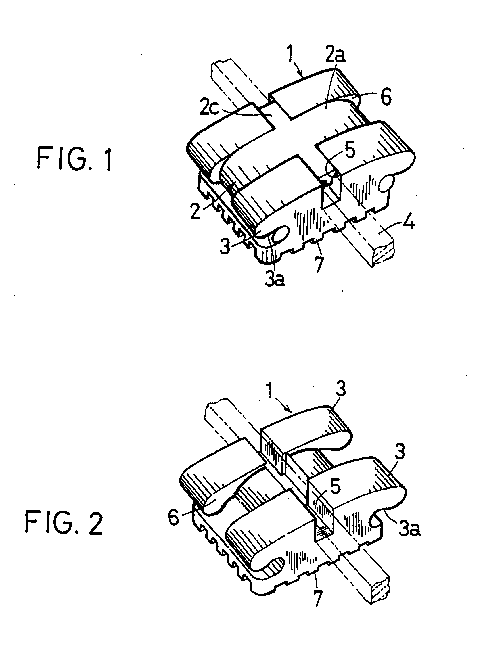
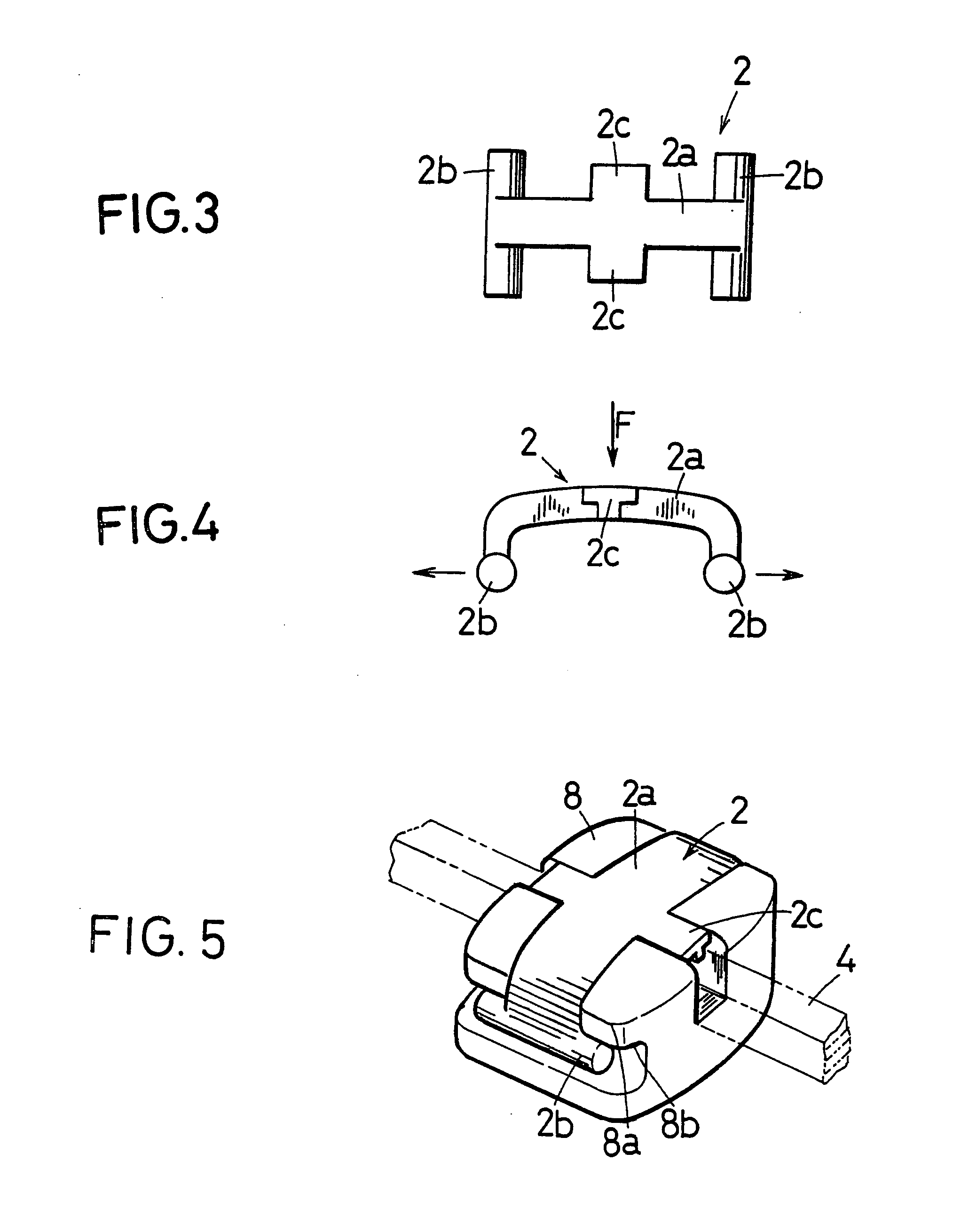
An orthodontic wire ligating member is engageable with an orthodontic bracket to retain an archwire inserted into a groove in the bracket. The ligating member is an elastically deformable member made of a synthetic resin and has at least two spaced engaging portions detachably engageable with the bracket, and a back portion integral with the engaging portions and elastically deformable flexibly to engage the bracket to retain the archwire. Thus, the friction between the archwire and the bracket slot is minimized, and the archwire is retained in a friction-free or low-friction state.

Description

[0001] 1. Field of the Invention[0002] The present invention relates to an orthodontic wire ligating member for use in orthodontic treatment. More particularly, the present invention relates to an orthodontic wire ligating member made of a synthetic resin and engaged with a bracket to retain an archwire.[0003] 2. Description of the Related Art[0004] Orthodontic treatment methods using brackets, tubes, etc. to correct a row of improperly positioned teeth are well known. In a typical orthodontic method, brackets, for example, are bonded to teeth to shift the positions of the teeth gradually by applying thereto mechanical tension, i.e. pushing force, pulling force, twisting or other elastic restoring force, with an archwire attached to the brackets, thereby correcting the malpositioned teeth. In this treatment method, each bracket has a slot for engagement with an archwire formed in the center of the bracket body. In addition, wings are provided on the outside of the bracket body. Afte...

Claims


Application Information

Patent Timeline
IPC IPC(8): A23L23/00A61C7/28
CPCA61C7/28
Inventor MIYAJI, HIROAKIMACHIDA, KAZUOTAMURA, HAJIME
Owner DENTSPLY SANKIN KK
Learn More