

Gaming machine
a display device and gaming machine technology, applied in the field of display devices, can solve the problems of low resolution of image, coarse image, and low liquid crystal drive elemen
- Summary
- Abstract
- Description
- Claims
- Application Information
AI Technical Summary
Benefits of technology
Problems solved by technology
Method used
Image

Examples
first embodiment
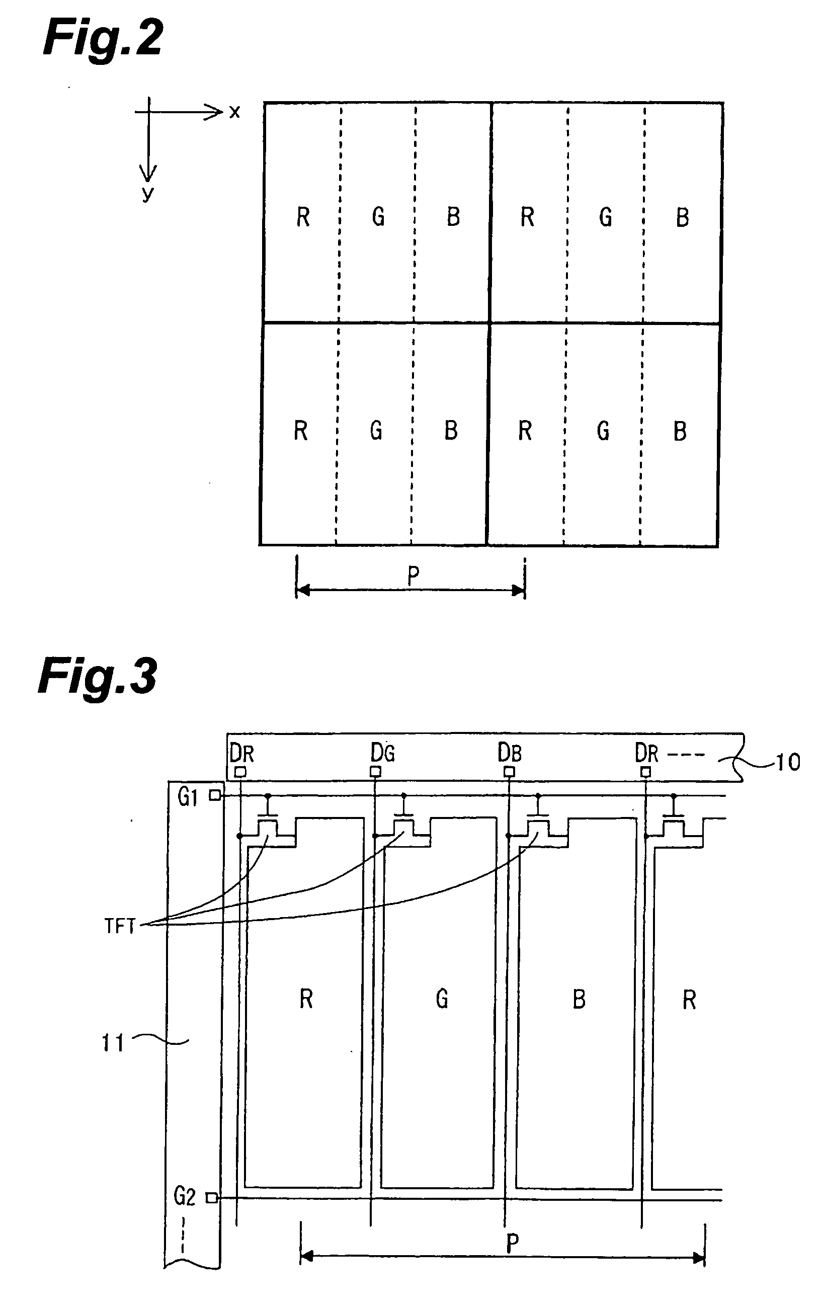
[0031] FIG. 1 is an explanatory diagram schematically showing a display screen of a display device according to a Note that, in this figure, only 4 pixels in 2.times.2 are shown in an enlarged manner.
[0032] As shown in this figure, in the display screen, a plurality of kinds of pixel electrodes R, G, and B that display three colors of R (red), G (green), and B (blue) respectively are arranged in matrix on an x-y plane, and pixel electrodes of the same color are arranged in the y direction and the same pattern is continuously arranged in an x direction to form a stripe. Moreover, in this display screen, a pixel unit is formed by arranging each kind of pixel electrodes R, G, and B, and one pixel is constituted by each pixel unit.
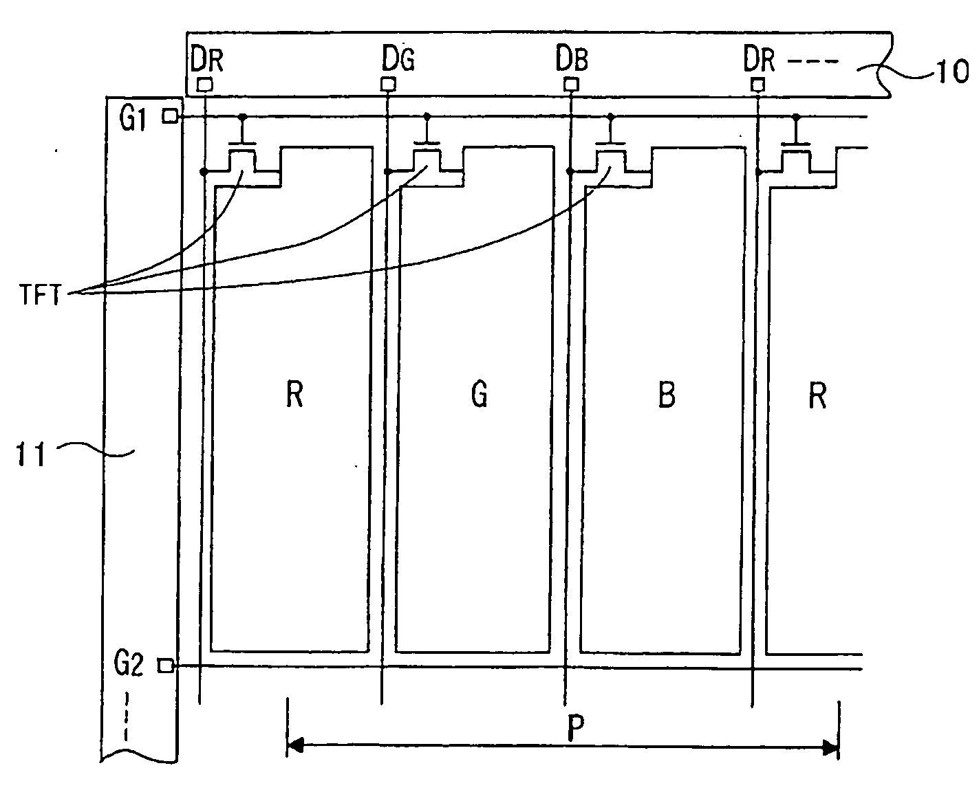
[0033] FIG. 2 shows a concrete configuration of this display screen. As shown in this figure, in the display device concerned, gate lines G1, G2, . . . that are wired in a horizontal direction in this figure (corresponding to the x direction in FIG. 1) and ar...
modified example
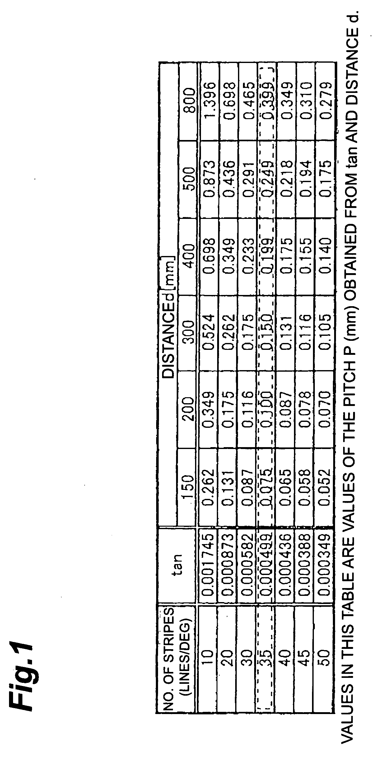
[0056] In addition, the value of the pitch P between pixel units is set up in this embodiment so that the above-mentioned formula (1) may be satisfied. Nevertheless, the value of the above-mentioned P may be set so that the pitch P (mm) and distance d (mm) may satisfy the following relationship:
P=tan(.pi. / 180 / 35).times.d / 2.times.(1+.alpha.) (2)
[0057] where the correction value .alpha. is .+-.0.1-0.2.
[0058] Going in detail of this, the distance d under normal use is 300-500 mm as mentioned above. Nevertheless, since a player's game posture changes every player or by a game status, it can be considered that a player approaches a gaming machine to about one half of the assumed distance d. Therefore, since pixels become conspicuous when a player approaches the gaming machine, the assumed distance d is set at one half in this modified example as shown in the above formula (2).
[0059] In addition, a pixel line becomes not conspicuous if the number of stripes is set to 35 or more. Neverthel...
second embodiment
[0062] Next, a second embodiment of this invention will be explained. This embodiment is characterized in that, in the display device explained in the first embodiment mentioned above, an output for one pixel from the information signal driver 10 which is drive control means, and each of pixel electrodes R, G, and B included in a pair of above-mentioned pixel units a and b (hereafter referred to as Ra, Ga, Ba, Rb, Gb, and Bb suitably) are connected in a one-to-one relationship.
[0063] Going in detail, as shown in FIG. 7, in the display device according to this embodiment, similarly to the first embodiment mentioned above, a plurality of kinds of pixel electrodes R, G, and B that display three colors of R (red), G (green), and B (blue) respectively are arranged in matrix on an x-y plane, and pixel electrodes of the same color are arranged in the y direction and the same pattern is continuously arranged in the x direction to form a stripe. Then, in this display screen, pixel units a an...
PUM
 Abstract
Description
Claims
Application Information