Liquid crystal display

a liquid crystal display and aperture ratio technology, applied in non-linear optics, instruments, optics, etc., can solve the problems of deteriorating side visibility deteriorating compared with front visibility, etc., to prevent the deterioration of the aperture ratio of liquid crystal displays

Active Publication Date: 2016-03-22
SAMSUNG DISPLAY CO LTD
View PDF14 Cites 0 Cited by
  • Summary
  • Abstract
  • Description
  • Claims
  • Application Information

AI Technical Summary

Benefits of technology

[0012]The present invention has been made in an effort to provide a liquid crystal display having advantages of preventing an aperture ratio of the liquid crystal display from deteriorating while electrically connecting a common voltage line transferring a common voltage to a common electrode to the common electrode and uniformly controlling a cell gap between an upper substrate and a lower substrate.
[0026]The liquid crystal display may further include a second extension disposed on a second side of the data line and extending opposite direction to the first extension. The second extension may extend substantially parallel to the data line and overlapping the data line. According to the exemplary embodiment of the present invention, it is possible to prevent an aperture ratio of the liquid crystal display from deteriorating while electrically connecting a common voltage line transferring a common voltage to a common electrode to the common electrode and uniformly controlling a cell gap between an upper substrate and a lower substrate.

Problems solved by technology

The liquid crystal display has an advantage of easily forming a thin display, but has a disadvantage in that side visibility deteriorates compared with front visibility.
Owing to the contact holes formed in the insulating layer and the opaque member for covering the column spacer, an aperture ratio of the liquid crystal display is deteriorated.

Method used


Image

  • Liquid crystal display
  • Liquid crystal display
  • Liquid crystal display

Examples


Embodiment Construction

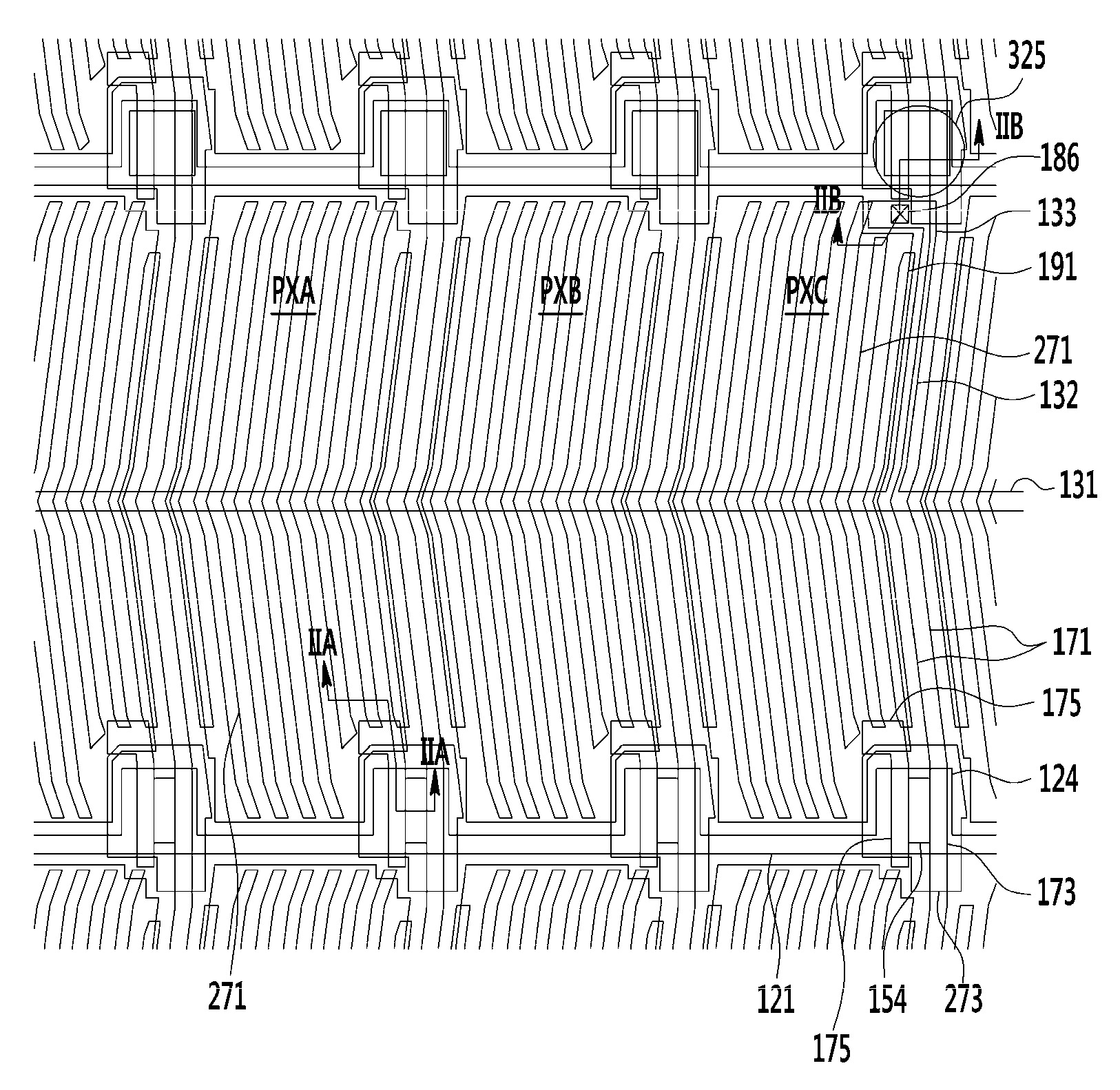
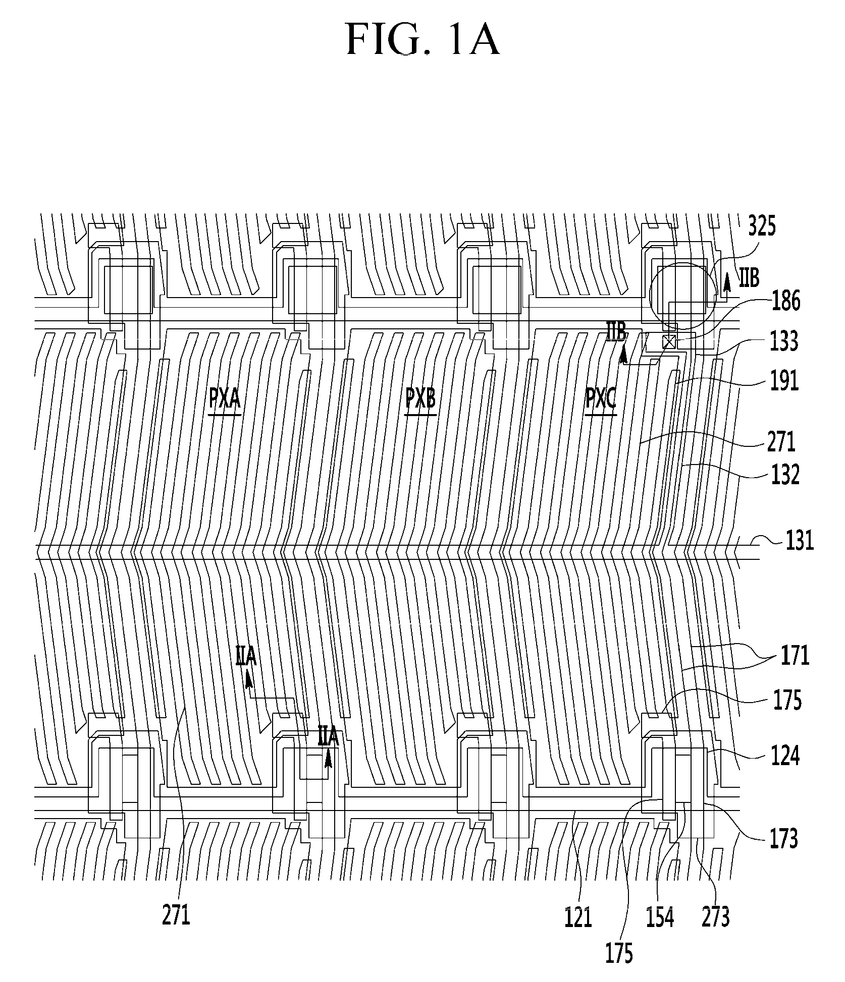
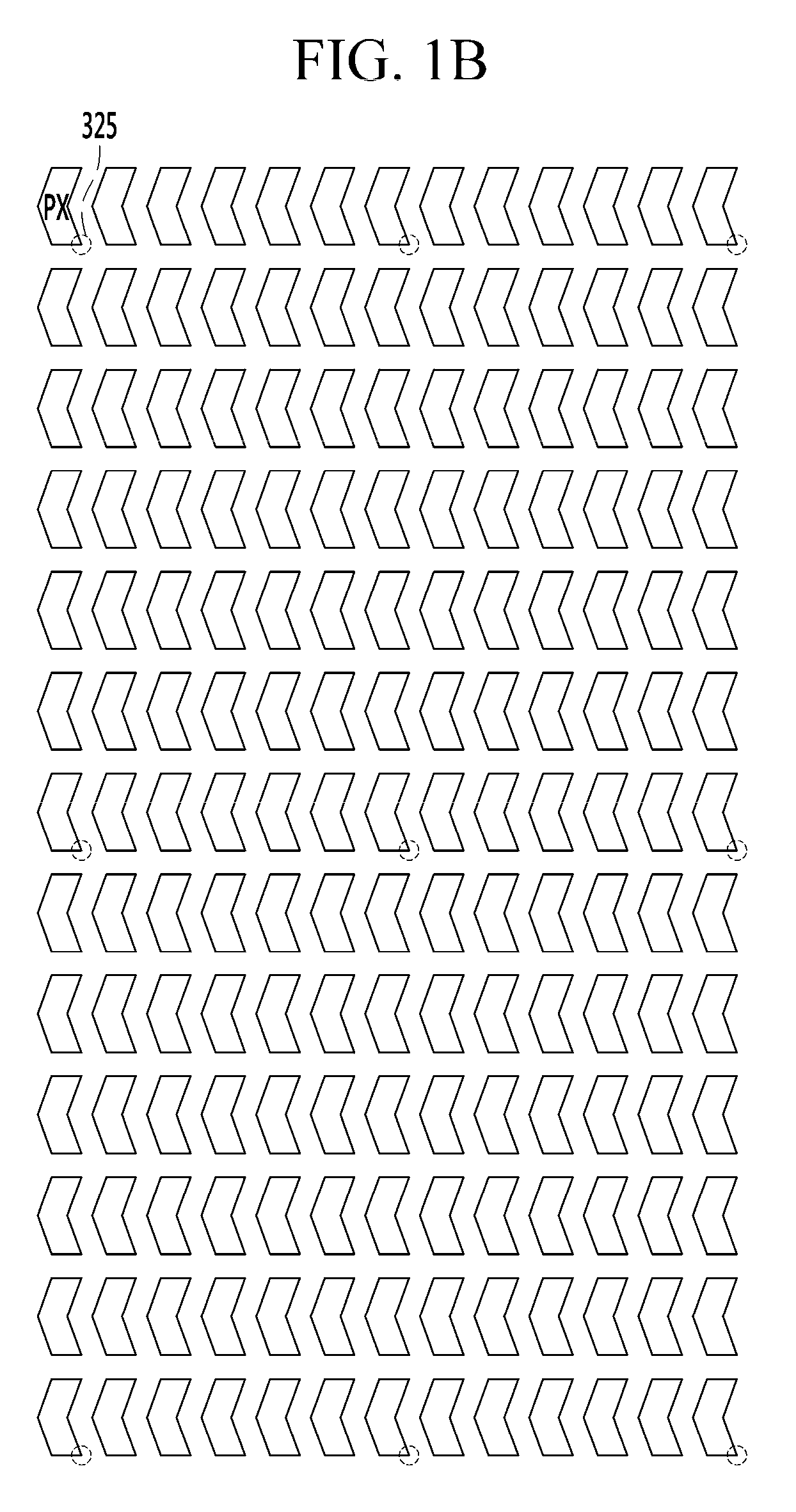
[0047]Hereinafter, embodiments of the present invention will be described in detail with reference to the accompanying drawings, in which exemplary embodiments of the invention are shown. As those skilled in the art would realize, the described embodiments may be modified in various different ways without departing from the spirit or scope of the inventive concept.

[0048]In the drawings, the thickness of layers, films, panels, regions, etc., may have been exaggerated for clarity. Like reference numerals designate like elements throughout the specification. It will be understood that when an element such as a layer, film, region, or substrate is referred to as being “on” another element, it can be formed directly on the other element or formed on the another element with one or more intervening elements therebetween. In contrast, when an element is referred to as being “directly on” another element, there are no intervening elements present.

[0049]A liquid crystal display according to ...


PUM

PropertyMeasurementUnit
angleaaaaaaaaaa
angleaaaaaaaaaa
angleaaaaaaaaaa

Abstract

Provided is a liquid crystal display including: a first substrate; a gate line, a data line, and a common voltage line formed on the first substrate; a first passivation layer formed on the gate line, the data line, and the common voltage line; and a pixel electrode and a common electrode formed on the first passivation layer and overlapping each other with a second passivation layer therebetween, and the common electrode is connected to the common voltage line through a common contact hole, and the common contact hole is disposed for every two or more dots.

Description

CROSS-REFERENCE TO RELATED APPLICATION[0001]This application claims priority to and the benefit of Korean Patent Application No. 10-2013-0082384 filed in the Korean Intellectual Property Office on Jul. 12, 2013, the entire contents of which are incorporated herein by reference.BACKGROUND[0002](a) Technical Field[0003]Embodiments of the present invention relate to a liquid crystal display.[0004](b) Description of the Related Art[0005]A liquid crystal display, which is one of the most common types of flat panel displays currently in use, is a display device which rearranges liquid crystal molecules of a liquid crystal layer by applying voltages to electrodes to control an amount of transmitted light.[0006]The liquid crystal display has an advantage of easily forming a thin display, but has a disadvantage in that side visibility deteriorates compared with front visibility. In order to solve the disadvantage, various types of alignments of the liquid crystal and driving methods have bee...

Claims


Application Information

Patent Timeline
Patent Type & Authority Patents(United States)
IPC IPC(8): G02F1/1343G02F1/1362G02F1/1335G02F1/1339
CPCG02F1/133512G02F1/13394G02F1/134363G02F1/136227G02F1/136209G02F1/1339G02F1/1343G02F1/136286G02F1/1368
Inventor CHANG, JONG WOONGSHIN, DONG HOLEE, YUN TAE
Owner SAMSUNG DISPLAY CO LTD
Why Eureka
Try Eureka