Hydraulic swing-controlling apparatus of work machine

Active Publication Date: 2012-05-31
KEJTERPILLAR R L
View PDF6 Cites 13 Cited by
  • Summary
  • Abstract
  • Description
  • Claims
  • Application Information

AI Technical Summary

Benefits of technology

[0016]According to the hydraulic swing-controlling apparatus of a work machine of the present invention (claim 1), the volume of relief during the swing operation can be held uniformly by controlling the discharge flow rate of the hydraulic pump based on a value which is obtained by subtracting the volume of hydraulic oil to be relieved from the required flow rate set based on the amount of the swing operation. This can reduce the relief losses at the beginning of the swing motion and enhances the energy efficiency, for example.
[0017]According to the hydraulic swing-controlling apparatus of a work machine of the present invention (claim 2), the volume of relief is estimated to be a negative value if the hydraulic pressure is lower than the relief pressure, hence, the appropriate flow rate can be inc

Problems solved by technology

Since a work machine has a high moment of inertia, the hydraulic pressure in an oil-hydraulic circuit becomes extre

Method used


Image

  • Hydraulic swing-controlling apparatus of work machine
  • Hydraulic swing-controlling apparatus of work machine
  • Hydraulic swing-controlling apparatus of work machine

Examples


Example

[0023]An embodiment of the present invention will be described below with reference to the drawings.

[1. Circuit Configuration]

[1-1. Swing Oil-Hydraulic Circuit L1]

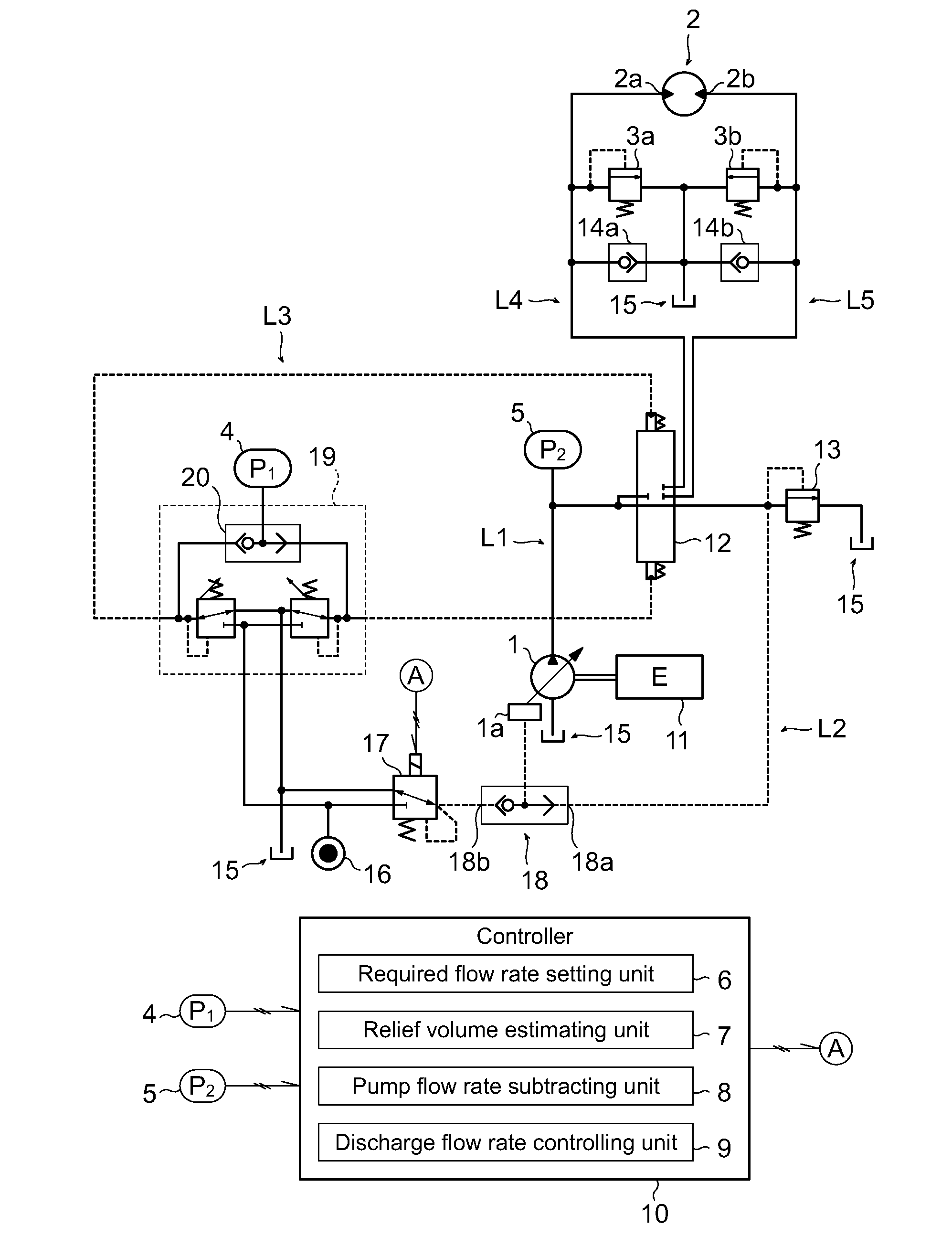
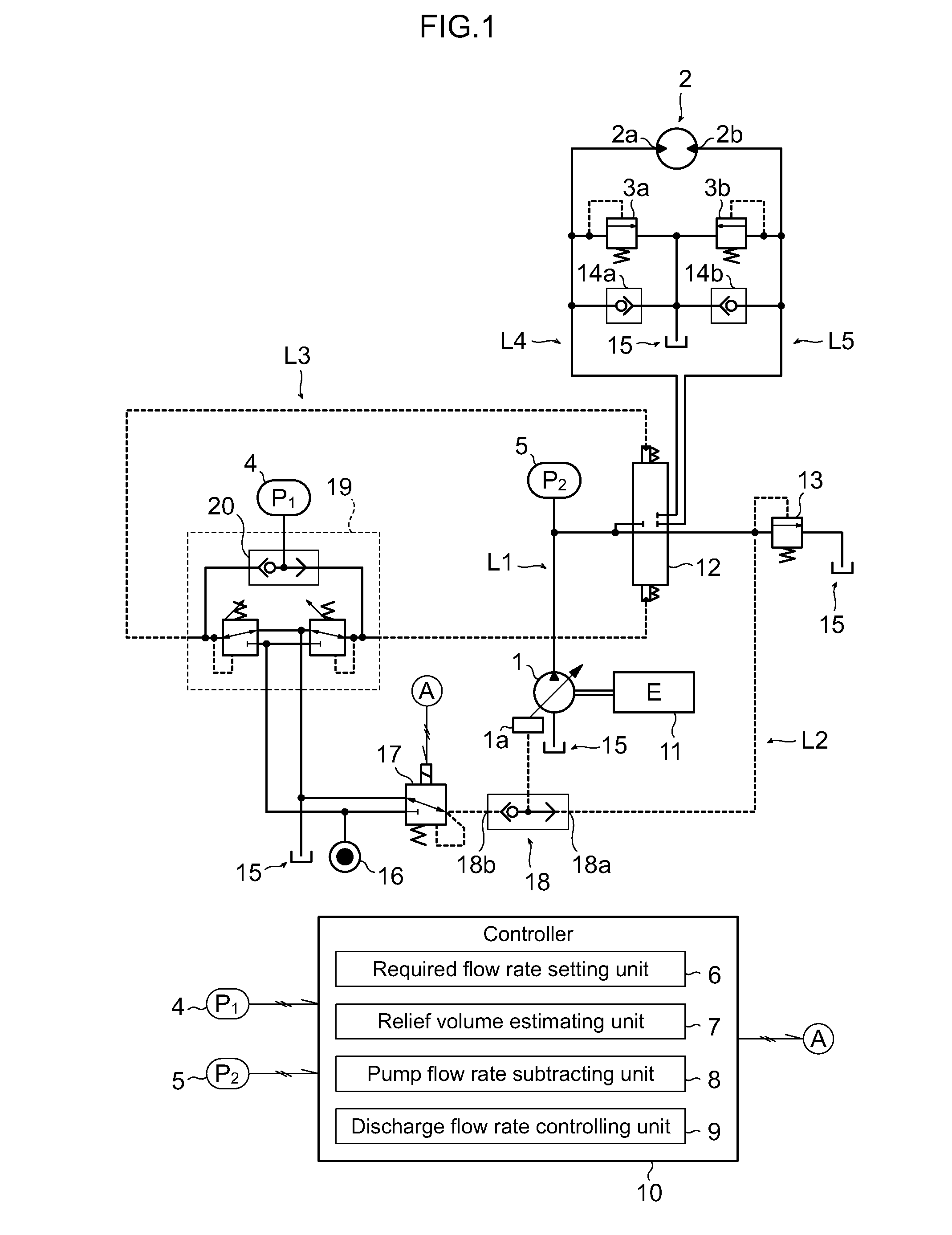
[0024]The present invention is applied to an oil-hydraulic circuit of a hydraulic excavator shown in FIG. 1. The drawing schematically illustrates the circuit relating to a swing motor 2 which swings the revolving supra-structure of the hydraulic excavator in a horizontal direction relative to a base carrier and circuits relating to other actuators are omitted. Note that this hydraulic excavator also includes other actuators, for example, a hydraulic cylinder relating to the drive of general front work equipment such as a boom device and an arm device.

[0025]This oil-hydraulic circuit includes a swing oil-hydraulic circuit L1 which supplies hydraulic oil to a swing motor 2, a negative control circuit L2, and an operation pilot circuit L3 of the swing motor 2.

[0026]A hydraulic pump 1, a swing motor 2, and a control valve 12 ...


PUM


Abstract

In a work machine including a hydraulic pump (1), a swing motor (2), and swing relief valves (3a and 3b), the amount of the swing operation (P1) related to the swing motion of the swing motor (2) is detected, and the hydraulic pressure (P2) supplied from the hydraulic pump (1) to the swing motor is also detected. Additionally, the required flow rate (FR) of hydraulic oil required for the swing motor (1) is set based on the amount of the swing operation (P1). In addition, the volume of relief (FE) is estimated from the hydraulic pressure (P2) based on the override characteristics of the swing relief valves (3a and 3b). The discharge flow rate of the hydraulic pump (1) is controlled based on the value obtained by subtracting the volume of relief (FE) from the required flow rate (FR).

Description

TECHNICAL FIELD[0001]The present invention relates to a power controller of a hydraulic pump for a swing motion of a work machine.BACKGROUND ART[0002]In a work machine, such as a hydraulic excavator, an oil-hydraulic motor can swing a revolving upper-structure on a base carrier. Since a work machine has a high moment of inertia, the hydraulic pressure in an oil-hydraulic circuit becomes extremely high and causes the relief losses of hydraulic oil while the oil-hydraulic motor is starting and accelerating. A variety of techniques have been proposed for reducing such relief losses.[0003]For example, Patent Literature 1 discloses a technique which decreases the discharge flow rate of a hydraulic pump to reduce relief losses during operation of a swing motor. This technique involves detection of a pilot pressure from a pilot valve linked to a swing lever, detection of a hydraulic pressure over the circuit between a flow rate control valve and the swing motor, and control of a swash plat...

Claims


Application Information

Patent Timeline
IPC IPC(8): F16D31/02
CPCE02F9/2235E02F9/123E02F9/2285E02F9/2296F04B49/002F15B2211/20546F15B2211/3051F15B2211/50518F15B2211/50527F15B2211/6054F15B2211/6309F15B2211/6316F15B2211/65F15B2211/7058E02F9/2282E02F9/12E02F9/22F15B11/00
Inventor YOSHINO, TETSUYAAKIYAMA, SEIICHIKANENAWA, YUYA
Owner KEJTERPILLAR R L
Why Eureka
Try Eureka