Cooling device for cylindrical, coupleable LED modules

Active Publication Date: 2013-05-09
HERAEUS NOBLELIGHT GMBH
View PDF4 Cites 13 Cited by
  • Summary
  • Abstract
  • Description
  • Claims
  • Application Information

AI Technical Summary

Benefits of technology

[0015]The object of the invention is to solve these problems. In particular, a uniform control of the temperature of the LED lamp or the LED modules

Problems solved by technology

The requirement of a mechanically robust holder and protective device for the bulb lamps also involves disadvantages, because these protective elements cause shadows that are significant, in particular for small pipe diameters.
The combination of the usually minimal available space for the lamp of a curing device for pipe rehabilitation and the required high power densities represents a great challenge for the structure and the function of a cooling body of such an LED lamp.
Such narrow LED lamps, which have linear constructions and are used, for example, in pipes or other environments that are tightly limited in terms of space, always have the problem that there is little space for additional parts used for cooling the LED lamps or LED modules of the LED lamps.
The same problem also occurs in narrow curing devices, which have linear constructions and in which the parts must be heated in the narrow space to an operating tempera

Method used


Image

  • Cooling device for cylindrical, coupleable LED modules
  • Cooling device for cylindrical, coupleable LED modules
  • Cooling device for cylindrical, coupleable LED modules

Examples


Embodiment Construction

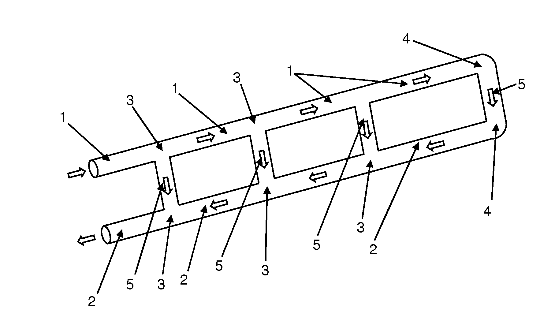
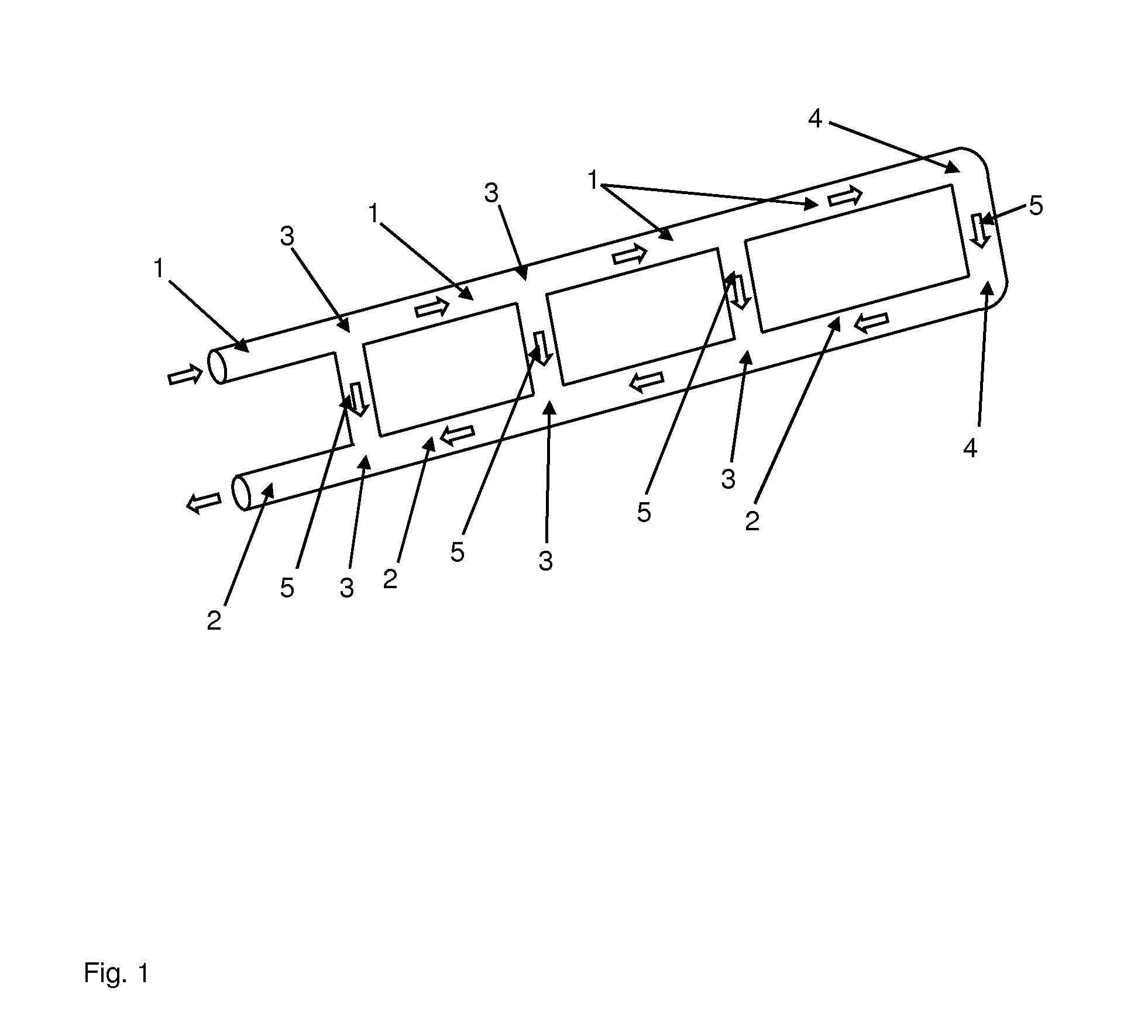
[0093]FIG. 1 shows a schematic view of a device according to an embodiment of the invention for controlling the temperature of an LED lamp or LED modules of an LED lamp and sketches a cooling or heating circuit. The device comprises a supply line (1) and a return line (2) that are both divided into different sub-areas. The supply line (1) and the return line (2) are formed by pipes. Between each of the sub-areas of the supply line (1) and the return line (2) there are three T-pieces (3). At the end of the supply line (1) and at the beginning of the return line (2) there is an L-piece (4). The T-pieces (3) and the L-pieces (4) are likewise formed by pipes. Between every two adjacent T-pieces (3) of the supply line (1) and the return line (2) and the two L-pieces (4) there are heat exchangers (5) that have tubular constructions.

[0094]All of the pipe pieces (1, 2, 3, 4, 5), that is the supply line parts (1), the return line parts (2), the T-pieces (3), the L-pieces (4), and the heat ex...


PUM


Abstract

A device and method are provided for controlling the temperature, in particular for cooling, of an LED lamp or LED modules of an LED lamp, e.g., for curing a light-cured pipe. The device includes: a fluid supply line and multiple heat exchangers connected to the supply line; multiple LEDs coupled to each heat exchanger with respect to heat transfer; and a fluid return line. The fluid supply and return lines are connected to each other in a fluid-tight manner by various combinations of L-pieces and T-pieces in or at the ends of the fluid supply and the return lines, so that the fluid flows from the LEDs in a spatially separated way and the fluid supply and return lines have at least two parallel fluid connections to each other, the heat exchangers being arranged in the fluid connections or constituting the fluid connections.

Description

CROSS-REFERENCE TO RELATED APPLICATIONS[0001]This application is a Section 371 of International Application No. PCT / EP2011 / 003317, filed Jul. 5, 2011, which was published in the German language on Jan. 19, 2012, under International Publication No. WO 2012 / 007115 A1 and the disclosure of which is incorporated herein by reference.BACKGROUND OF THE INVENTION[0002]The invention relates to a device for controlling the temperature, in particular for cooling, of an LED lamp or LED modules of an LED lamp, wherein the device comprises a supply line for feeding a fluid and multiple heat exchangers connected to the supply line, wherein multiple LEDs are arranged on each heat exchanger and are coupled to the heat exchanger with respect to heat transfer, so that the fluid can control the temperature, in particular cool, the LED lamp or the LED modules. The invention also relates to a method for controlling the temperature, in particular cooling, of an LED lamp or at least two LED modules of an L...

Claims


Application Information

Patent Timeline
IPC IPC(8): F21V29/00
CPCF21V29/248F21K9/20F21Y2115/10F21Y2107/30F21V29/51F21V29/85F21V29/58
Inventor PEIL, MICHAELOSWALD, FLORINMAIWEG, HARALDWILLER, BERND
Owner HERAEUS NOBLELIGHT GMBH
Why Eureka
Try Eureka