Method and system for dewatering particulate materials

a technology of particulate materials and dewatering systems, which is applied in the direction of fluid pressure measurement, liquid/fluent solid measurement, peptide measurement, etc., can solve the problems of deterioration of materials, large amount of energy used, unstable stockpiling and heavy transportation or disposal,

Inactive Publication Date: 2004-10-28
UNITED STATES OF AMERICA THE AS REPRESENTED BY THE SEC OF THE ARMY
View PDF4 Cites 3 Cited by
  • Summary
  • Abstract
  • Description
  • Claims
  • Application Information

AI Technical Summary

Problems solved by technology

Long-term continuation of this saturated condition is undesirable and may lead to deterioration of the materials.
Similarly, sludges, dredged spoils, and fine aggregates can become laden with moisture, making them unstable to stockpile and heavy to transport or dispose.
However, these procedures are very slow and utilize large amounts of energy.
Further, as with any process utilizing heat, there is a risk of thermally induced warping and cracking of the structure.
However, employing this method on any significant volume of particulate requires either a substantial number of pumps or a great deal of suction, as capillary forces in fine-grained materials make it difficult to extract water.
There are, however, practical drawbacks to the use of electro-osmotic dewatering systems.
First, conventional electro-osmotic systems are rather inefficient, and therefore relatively easily defeated by wet weather.
These films have a very high electrical resistance, leading to deterioration in the electrical characteristics of the system and lowered system efficiency.
A similar problem arises from the fact that the anodes of the system are subject to a high degree of electrolytic corrosion.
Where electrodes are installed specifically for dewatering, this corrosion results initially in reduced system efficiency, and, eventually, in complete electrical discontinuity at the electrode.
Alternatively, where the structure's internal reinforcing steel is used as the anode, heavy corrosion of the electrode is damaging to the structure itself.
Accumulated gases present another problem in existing electro-osmotic dewatering systems.
These accumulated gases may also react, producing an undesirable energetic event, such as a fire or explosion.
Extant electro-osmotic dewatering systems also require a great deal of space to install.
Prior art dewatering systems are also subject to encrustation in the extraction pipe.
This precipitate can obstruct or clog the slots or perforations in the extraction pipe.
Electrical isolation is also a problem with existing electro-osmotic dewatering systems.
If the surrounding soil is dewatered to such an extent that the resistance around the metal pipe increases, the dewatering circuit is effectively broken.
Anyone touching the metal pipe, or even an extraction pump attached to the system, is a better conductor to ground than the metal pipe, making extant systems rather dangerous, especially for systems that run at high voltages.

Method used


Image

  • Method and system for dewatering particulate materials
  • Method and system for dewatering particulate materials
  • Method and system for dewatering particulate materials

Examples


Embodiment Construction

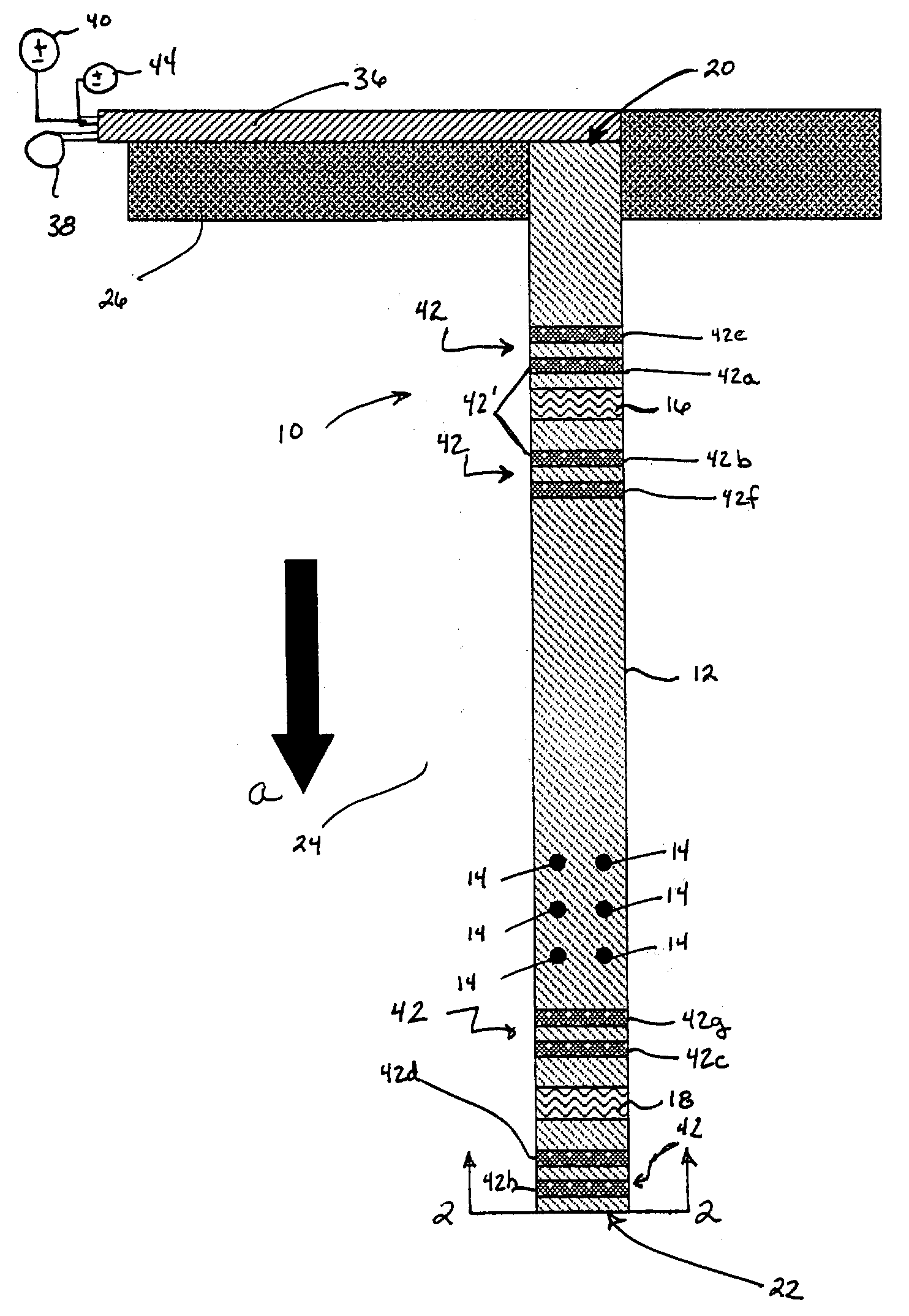
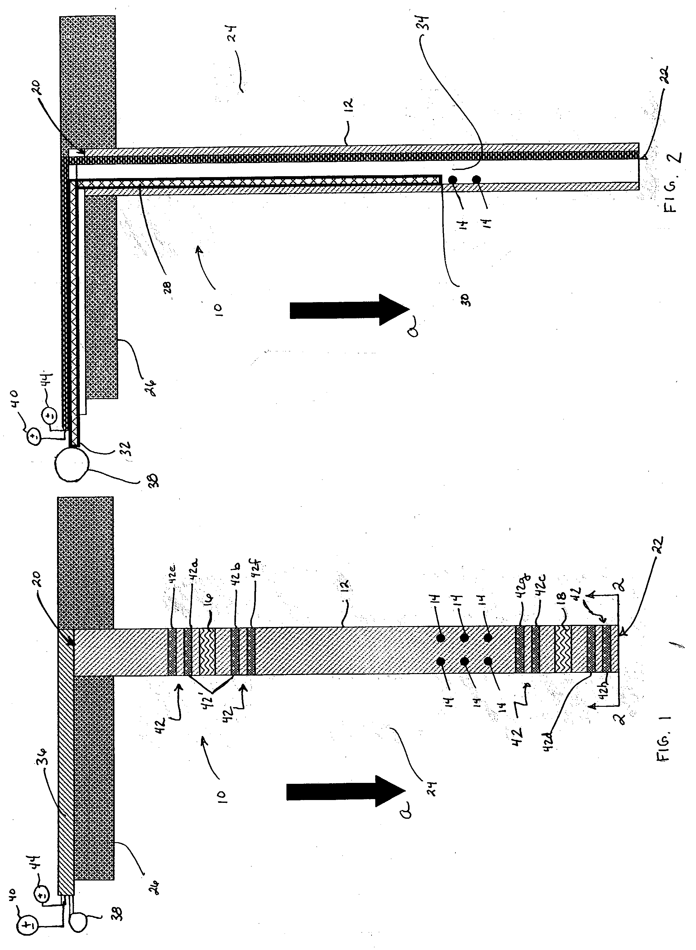
[0027] Referring now to the drawings, and specifically to FIGS. 1 and 2, there is shown a probe 10 for dewatering a particulate material according to the present invention. Dewatering probe 10 generally includes a non-conducting pipe 12 having a plurality of drainage holes or slots 14. An anode 16 and a cathode 18 are mounted on non-conducting pipe 12 adjacent opposing top and bottom ends 20, 22, respectively, thereof. Pipe 12 functions both as a sonde for mounting anode 16 and cathode 18 and as a well used to extract water that collects around the outside of and flows into pipe 12 via holes 14.

[0028] In FIGS. 1 and 2, probe 10 is shown oriented in a particulate material 24 beneath a concrete slab 26 such that anode 16 is above cathode 18. This substantially vertical orientation is preferred, as water will flow in the direction of arrowhead a due to both gravity and electro-osmotic forces, whereas an inverse configuration (that is, with cathode 18 above anode 16) would cause water f...


PUM

PropertyMeasurementUnit
voltageaaaaaaaaaa
voltagesaaaaaaaaaa
electricallyaaaaaaaaaa

Abstract

A system and method for dewatering particulate materials employs an improved dewatering probe generally including a single non-conducting pipe having a plurality of holes or slots, an anode mounted on the pipe adjacent one end of the pipe, and a cathode mounted on the pipe adjacent the opposite end of the pipe. The pipe serves as both a sonde for mounting the anode and cathode and as a well for extracting water that collects around the outside of the pipe and flows into the interior of the pipe through the holes or slots via gravitational and electro-osmotic forces. A pump may be used to extract both collected water and accumulated electrolytic gases from the pipe's interior. In embodiments, an array of guide electrodes is mounted on the pipe in addition to the anode and the cathode in order to deflect the major current flow out into the body of surrounding particulate materials. The guide electrodes also facilitate rapid depolarization of the probe. An array of probes according to the present invention may be employed as a system to dewater a volume of particulate.

Description

CROSS-REFERENCES TO RELATED APPLICATIONS[0001] Not Applicable.[0002] The invention described herein may be manufactured and used by or for the United States Government for governmental purposes without the payment of any royalties thereon.[0003] 1. Field of the Invention[0004] The present invention relates generally to dewatering devices, and, more particularly, to an improved active and electro-osmotic dewatering system.[0005] 2. Background Description[0006] Many common building and insulating materials have a capillary pore system that can become saturated with water. This is especially the case where the material, such as a building's foundation, is in contact with a particulate moisture source, such as soil. Long-term continuation of this saturated condition is undesirable and may lead to deterioration of the materials. Similarly, sludges, dredged spoils, and fine aggregates can become laden with moisture, making them unstable to stockpile and heavy to transport or dispose.[0007...

Claims


Application Information

Patent Timeline
Patent Type & Authority Applications(United States)
IPC IPC(8): B01D61/56C02F1/469C02F11/15E04B1/70
CPCB01D61/56C02F1/469C02F11/12C02F2201/4613C02F2201/4617E04B1/7007C02F11/15
Inventor MOREFIELD, SEAN W.WEISS, CHARLES A. JR.MALONE, PHILIP G.HOCK, VINCENT F.MCINERNEY, MICHAEL K.
Owner UNITED STATES OF AMERICA THE AS REPRESENTED BY THE SEC OF THE ARMY
Why Eureka
Try Eureka