Reinforced profile

a technology of reinforced profiles and profiles, applied in the field of reinforced profiles, can solve the problems of increasing the bending strength the need for covering or cladding, and the elastic instability of the construction element, so as to improve the adapted position, the compression strength of the compound element is increased, and the rigidity against bending can be increased.

Active Publication Date: 2004-11-04
TECH WOOD INT
View PDF54 Cites 43 Cited by
  • Summary
  • Abstract
  • Description
  • Claims
  • Application Information

AI Technical Summary

Benefits of technology

[0013] The wood particles or other, cellulose-containing particles in the thermoplastic synthetic material increase the E-modulus of said material considerably (various times higher, approximately 4-5 times to 4-8 times higher than standard polyethylene or polypropylene), as a result of which the interaction with reinforcement elements is enhanced. As a result of the high content of wood particles or other, cellulose-containing particles, etcetera, a high E-modulus of the composite material after cooling is obtainable, of more than approximately 6000 MPa (870,000 psi), in a preferred embodiment approximately 6000-12000 MPa (870,000-1,740,000 psi), in a further preferred embodiment even approximately 7000-9000 MPa (1,015,000-1,305,000 psi). Thus it can be achieved that the reinforcement elements--considered in transverse direction to it--are kept in place by bending the construction element used. As a result the moment of inertia of the construction element is preserved. In a thermoplastic material that is not provided with such a fraction of wood particles or other, cellulose-containing particles the reinforcement elements would be able to migrate in transverse direction when bent and thus get closer to the neutral line. This could cause elastic instability (`buckling`).
[0025] Preferably the additional elements are entirely enveloped or encapsulated by the composite material, so that the cooperation between the compound parts can be optimal.

Problems solved by technology

A drawback of such beams or profiles is that at locations where they can be seen, a covering or cladding has to be provided when the said space is not a storage or factory or production facility in order to avoid an unattractive appearance.
This could cause elastic instability (`buckling`).
This results in an increase of the bending strength of the construction element.

Method used


Image

  • Reinforced profile
  • Reinforced profile
  • Reinforced profile

Examples


Embodiment Construction

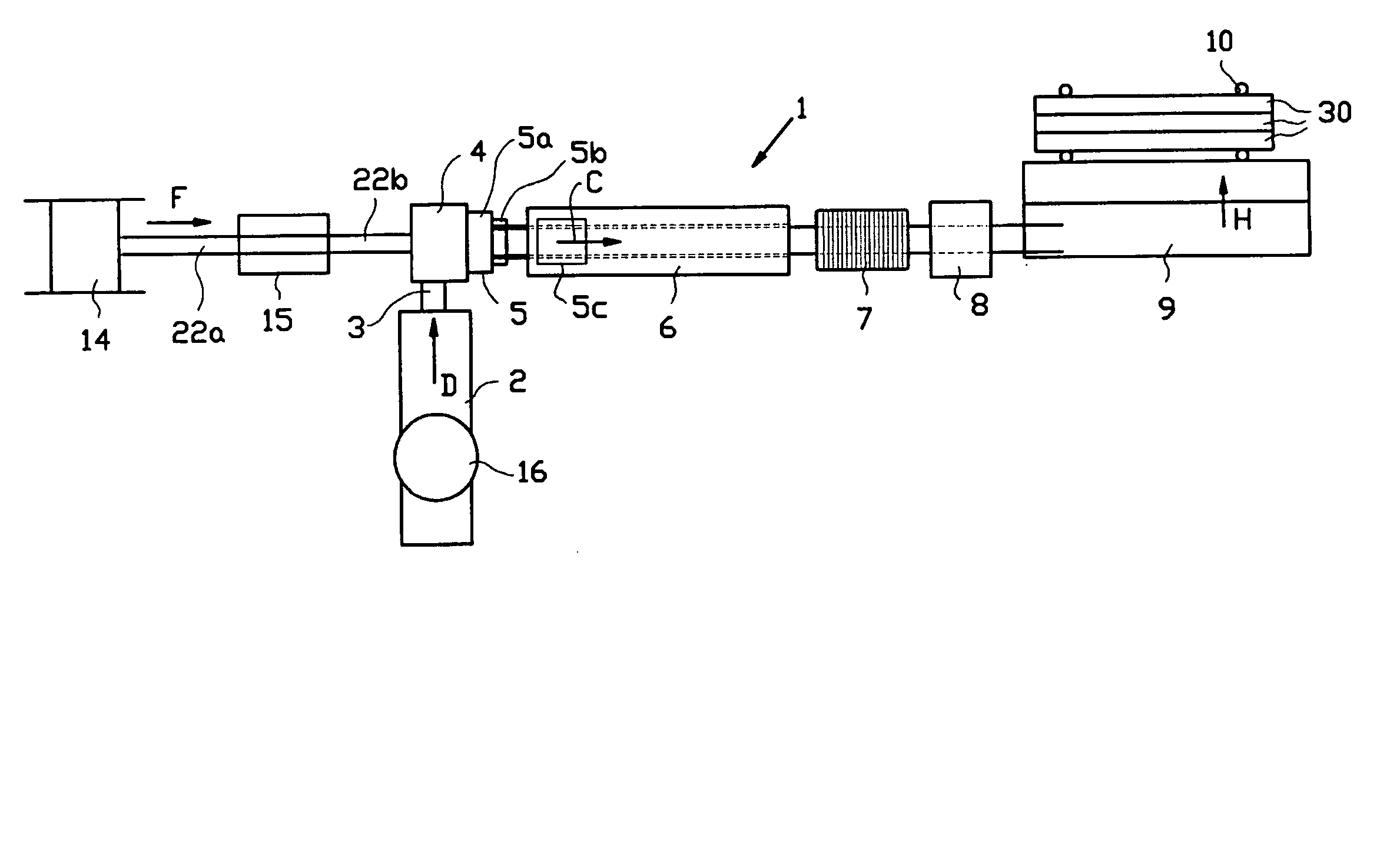
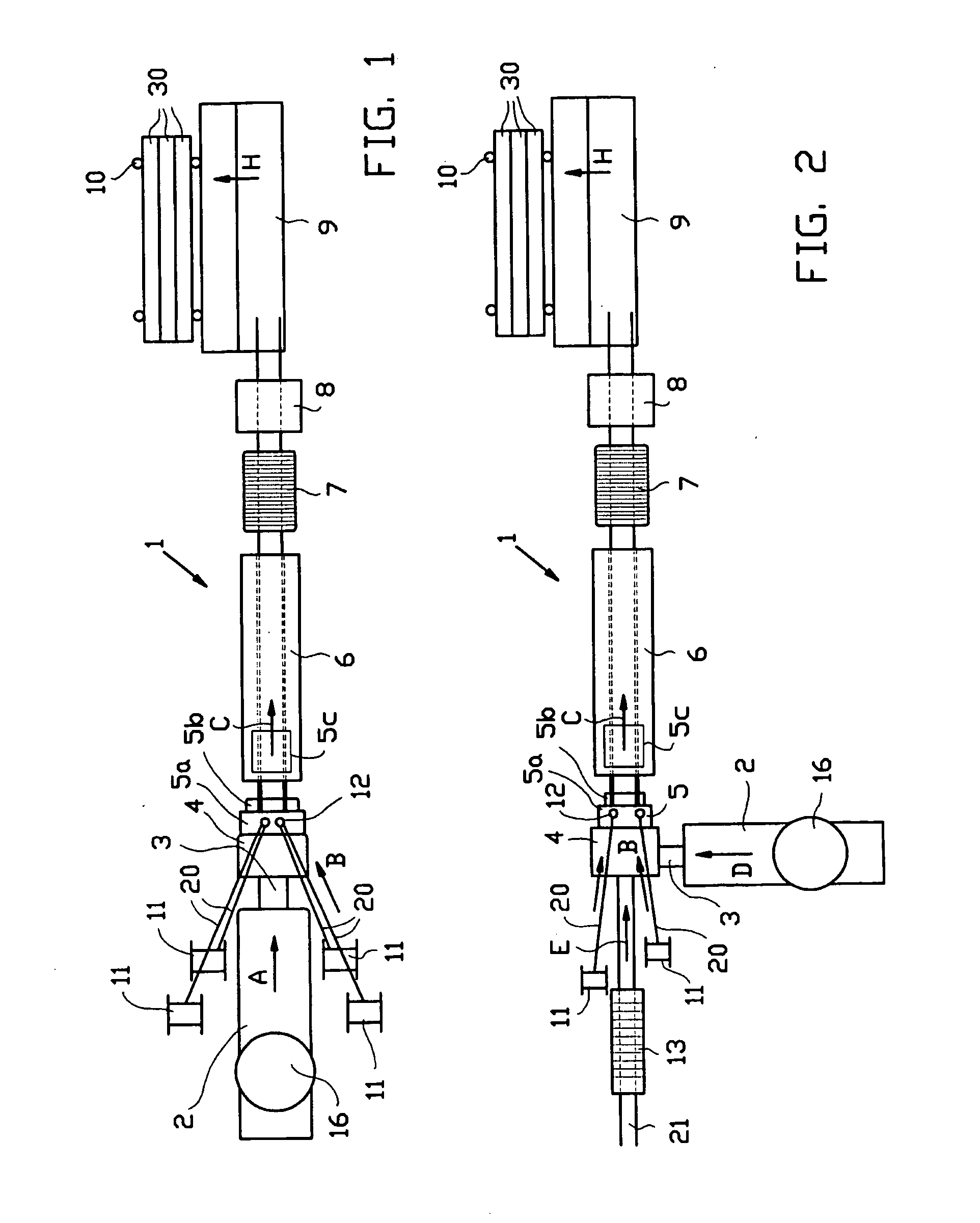
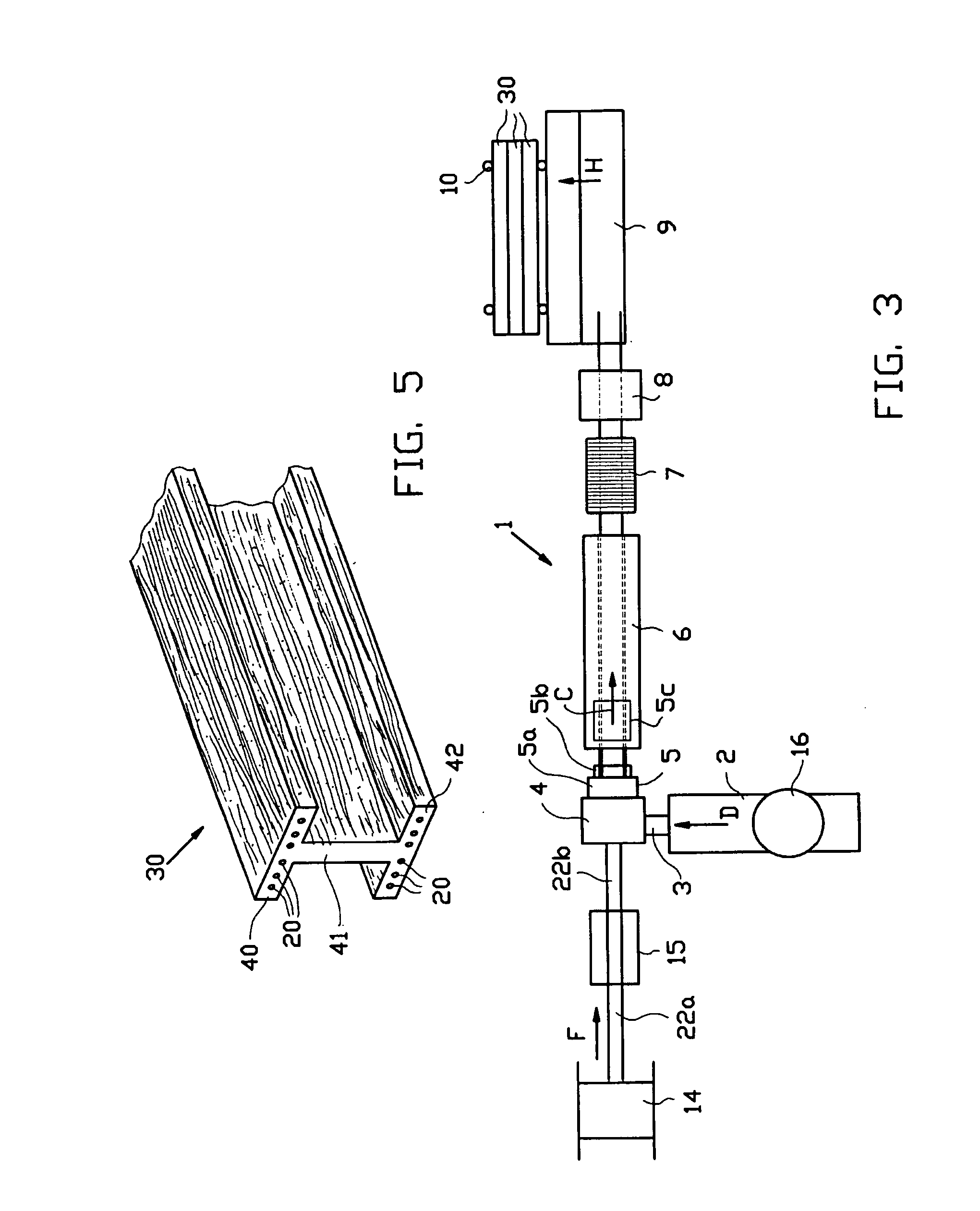
[0036] The set-up shown in FIG. 1 comprises an installation 1 comprising a pushtruder 2 having a feed 16, which via intermediate flange 3 merges into extrusion die 4. A fibre-orientating device is incorporated in the extrusion die 4. Downstream of the extrusion die 4, immediately contiguous to it, a shaping unit 5 is placed, wherein cooling facilities have also been incorporated. The shaping unit 5 comprises a pre-shaping die 5a, in which the profile is substantially shaped, and a cooling / shaping die 5b attached to the die 5a, in which the shape is further established. Downstream of the shaping unit 5 a post-cooling unit or tank 6 is positioned, in which optionally a further cooling / calibrating die 5c may be positioned, immersed in the coolant in the cooling unit or tank 6, at the upstream end thereof. Furthermore a tension control unit 7 is positioned, and downstream thereof there is a sawing unit 8. Downstream thereof a discharge table 9 is positioned, from where cut to length ele...


PUM

PropertyMeasurementUnit
lengthaaaaaaaaaa
lengthaaaaaaaaaa
diameteraaaaaaaaaa

Abstract

A method for manufacturing a compound construction element, in an extrusion process wherein a composite material is pressed through an extrusion die, which composite material includes a matrix of thermoplastic synthetic material including wood particles or other, cellulose containing particles in a content on the order of 50% by weight or more, wherein also one or more elongated additional elements are passed through the extrusion die, which additional elements are brought into tight engagement with the composite material, after which the compound element is shaped and preferably cooled in a die.

Description

[0001] This application claims the benefit of U.S. Provisional Application No. 60 / 459,167, filed Mar. 31, 2003, which is relied on and incorporated by reference.[0002] The invention relates to a method for manufacturing reinforced profiles or sections, such as beams.[0003] The invention particularly relates to such profiles for use at locations where they are visible and can be seen.PRIOR ART[0004] Reinforced profiles are widely known, for instance in the form of reinforced concrete beams. They are placed at locations where the forces from structures that are situated above them, for instance roofs, have to be absorbed and transferred to structures that are situated below them, such as columns. Such reinforced profiles serve as an alternative to steel beams or wooden joists.[0005] A drawback of such beams or profiles is that at locations where they can be seen, a covering or cladding has to be provided when the said space is not a storage or factory or production facility in order t...

Claims


Application Information

Patent Timeline
Patent Type & Authority Applications(United States)
IPC IPC(8): B27N3/28E04C3/04E04C3/28E04C3/29E04C5/07
CPCB27N3/28Y10T428/29B29C47/003B29C47/0057B29C47/027B29C47/86B29K2023/06B29K2023/12B29K2027/06B29K2105/08B29K2105/101B29K2711/14B29L2031/003E04C3/28E04C3/29E04C5/07E04C2003/043E04C2003/0452E04C2003/0465E04C2003/0469Y10T428/24132Y10T428/24058B29C47/0028B29C48/05B29C48/11B29C48/12B29C48/0018B29C48/156B29C48/79B29C48/86B29C48/87B29C48/919B29C48/90B29C48/905
Inventor VAN DIJK, DIRKSCHOENMAKER, JOHAN ALBERT
Owner TECH WOOD INT
Why Eureka
Try Eureka