
Mobile communication system

a mobile terminal and communication system technology, applied in the field of mobile communication systems, can solve the problems of increasing the time for reception processing and power consumption, the user's mental anguish, and the inability of the mobile terminal to select only the necessary area information

Inactive Publication Date: 2004-11-11
RPX CORP
View PDF5 Cites 3 Cited by
  • Summary
  • Abstract
  • Description
  • Claims
  • Application Information

AI Technical Summary

Benefits of technology

The present invention aims to provide a mobile communication system that can efficiently distribute necessary area information to mobile terminals in a limited manner, while improving the use efficiency of resources and saving the whole system.

Problems solved by technology

Moreover, the mobile terminal cannot select only the necessary area information, being information relating to the cell in which the mobile terminal exists, with respect to the area information distributed from the radio Node.
Therefore, the mobile terminal also receives unnecessary area information, and hence the time for reception processing and power consumption increase, and according to circumstances, mental anguish is given to the user of the mobile terminal.
On the other hand, since the radio Node distributes unnecessary area information to the mobile terminal, useless resources relating to the distribution of the area information increase, thereby increasing a load.
Therefore, distribution of the area information becomes a main cause resulting in insufficient resources causing congestion.
With such a method, the information transmission apparatus must be installed other than the radio Node for ordinary communication performed by the mobile terminal, which requires the cost for equipment investment.

Method used


Image

  • Mobile communication system
  • Mobile communication system
  • Mobile communication system

Examples


Embodiment Construction

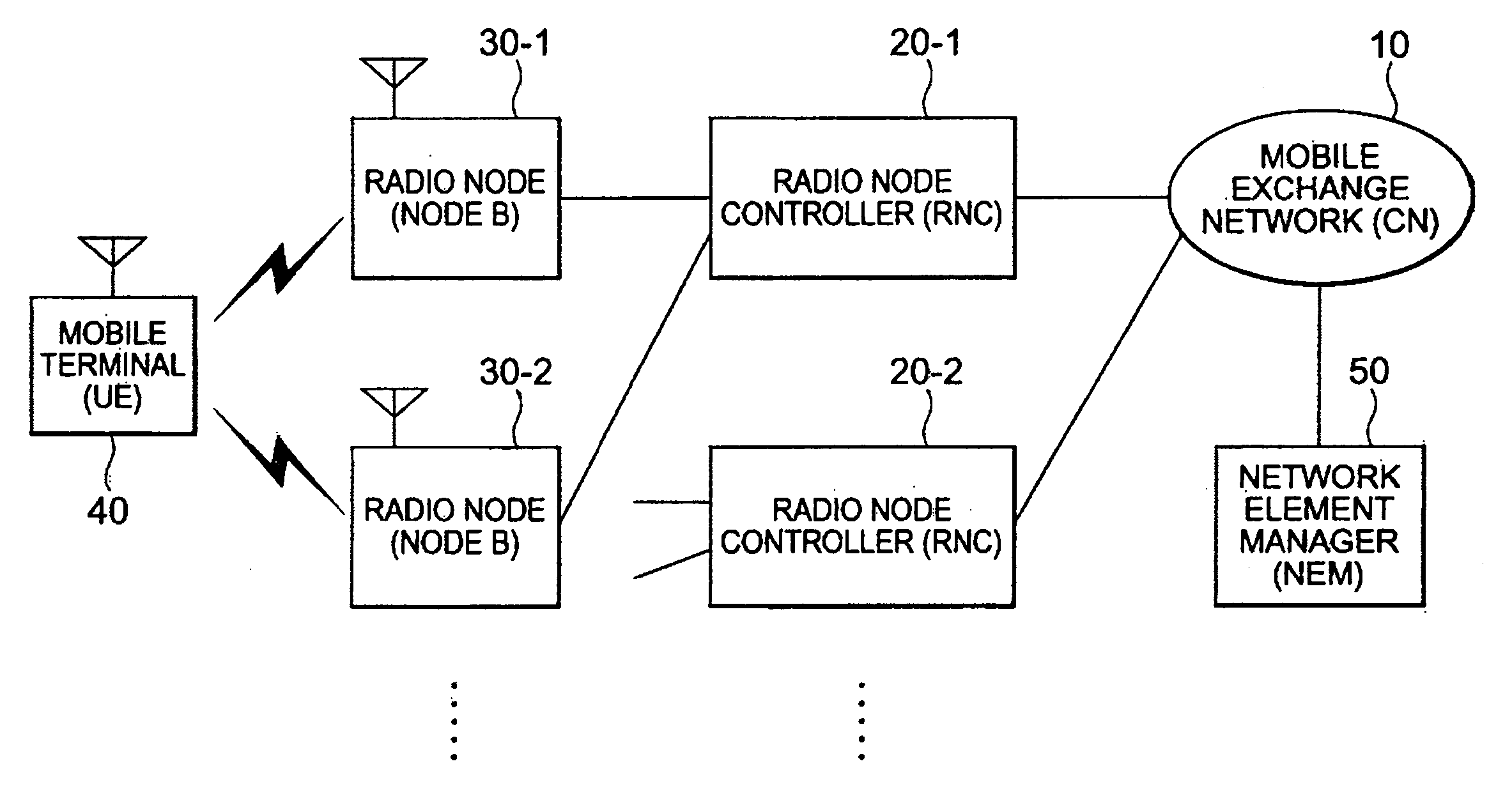
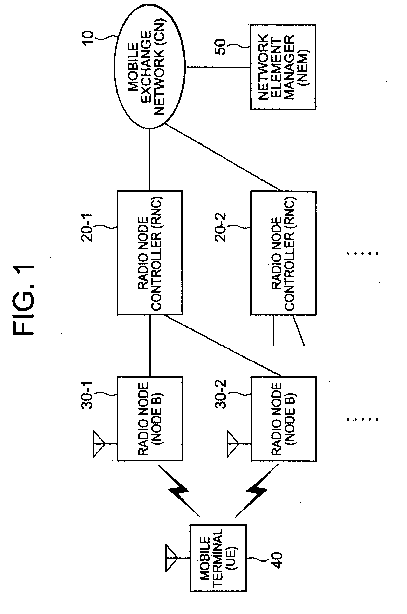
[0024] FIG. 1 is a system block diagram showing the configuration of the mobile communication system according to the present invention.

[0025] As shown in FIG. 1, the mobile communication system according to the present invention includes a network element manager (NEM) 50, a mobile exchange network (CN) 10, a plurality of radio Node controllers (RNC) 20-1 and 20-2, a plurality of radio Nodes (Nodes B) 30-1 and 30-2, and a mobile terminal (UE) 40 performing radio communication with the radio Nodes 30-1 and 30-2 in a cell (or a sector) included in the radio Nodes 30-1 and 30-2.

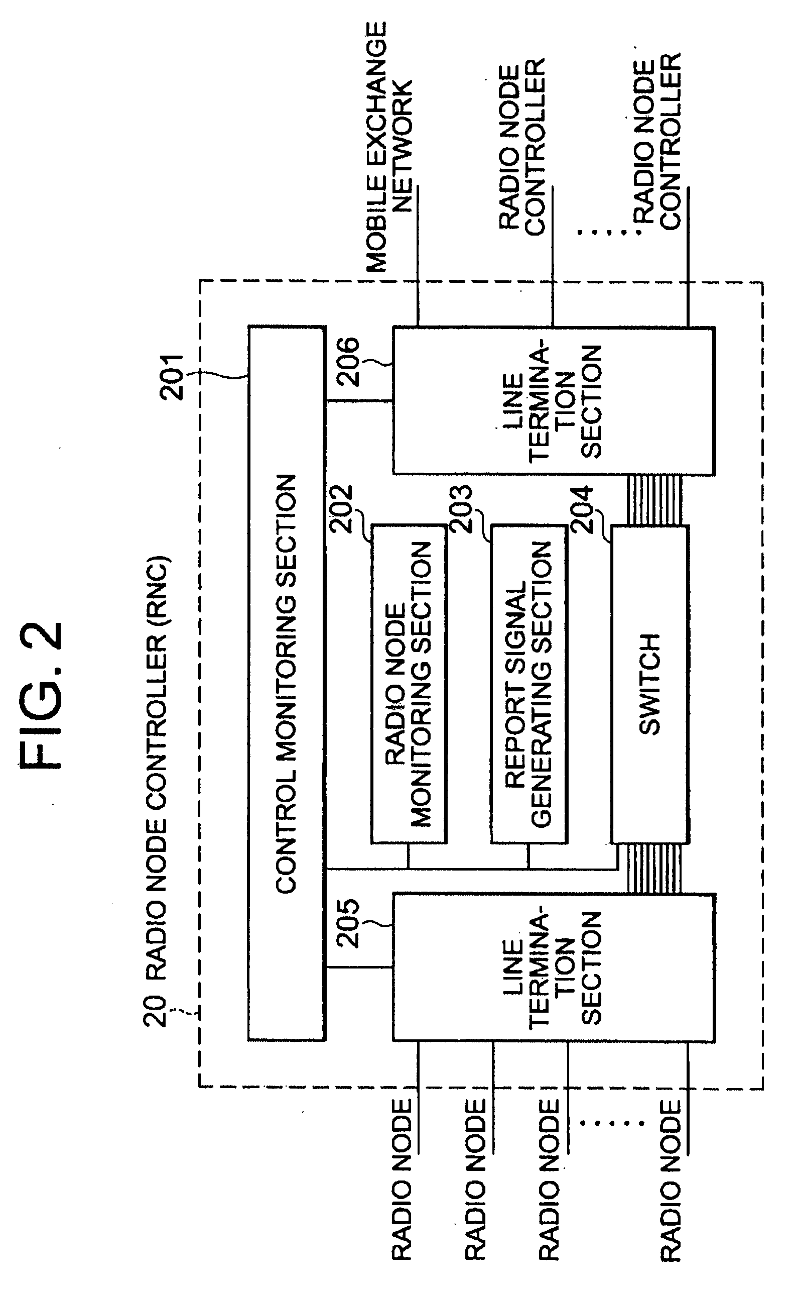
[0026] The mobile terminal 40 has a Radio transmitter-receiver, and is generally a mobile phone or personal information-processing equipment, which is carried by a user and can be moved geographically, but also includes a fixed telephone fixed and installed geographically. The radio Node controllers 20-1 and 20-2 are the host apparatus with respect to the radio Nodes 30-1 and 30-2, and the mobile exchange netwo...


PUM


Abstract

To provide a mobile communication system which can distribute area information from a radio Node to a mobile terminal in a unit of cell. A mobile communication system comprising: a radio Node having a plurality of cells; host apparatus connected to the radio Node so as to be able to communicate information with the radio Node; and a mobile terminal receiving information distributed from the radio Node, wherein area information different for each cell is distributed from the radio Node to the mobile terminals 40 existing in the cell included in the radio Node, the area information is transmitted, together with control information including type information added according to a content of the area information, from the host apparatus to the radio Node, and the cell to be distributed with the information is determined based on the type information.

Description

[0001] The present invention relates to a mobile communication system, and more specifically, relates to a mobile communication system having a radio Node having a plurality of cells (or sectors), host apparatus connected to the radio Node so as to be able to communicate information with the radio Node, and a mobile terminal receiving information distributed from the radio Node, wherein area information different for each cell is distributed from the radio Node to the mobile terminal existing in the cell included in the radio Node. The invention is based on a priority application JP 2003-128568 which is hereby incorporated by reference.PRIOR ART[0002] For example, the method of distributing to a mobile terminal the area information, being information relating to a specific communication area in the mobile communication system, in which the mobile terminal exists, includes a method of carrying the area information in report information in a unit of radio Node and distributing the are...

Claims


Application Information

Patent Timeline
Patent Type & Authority Applications(United States)
IPC IPC(8): H04M11/08H04W4/06H04M3/487H04W4/02
CPCH04W4/02H04W4/06H04W28/0226
Inventor SATOU, HIROTOSHIOTSUKA, MASAOMATSUSHITA, KOJINAITO, SACHIKOTOMOZAWA, HIROSHI
Owner RPX CORP
Learn More