Dielectric resonator filter

a dielectric resonator and filter technology, applied in the direction of resonators, waveguides, line-transmission, etc., can solve the problems of inability to provide diagonal cross coupling, the coupling structure cannot be located between adjacent non-sequential cavities, and the coupling structure cannot be located at the outer wall

Active Publication Date: 2004-11-18
ALCATEL LUCENT SAS
View PDF7 Cites 3 Cited by
  • Summary
  • Abstract
  • Description
  • Claims
  • Application Information

AI Technical Summary

Benefits of technology

0012] Another object of the invention is to provide an optimum thermal path for evacuation of the heat that is generated during high power operation since the inner wall come into electric contact with the coupling m

Problems solved by technology

A disadvantage with the microwave filter known from U.S. Pat. No. 6,255,919 is that the coupling structure can only be located at the outer wall and is always perpendicular to the wave path.
On the other hand, the coupling structure can never be located between non-ad

Method used


Image

  • Dielectric resonator filter
  • Dielectric resonator filter
  • Dielectric resonator filter

Examples


Embodiment Construction

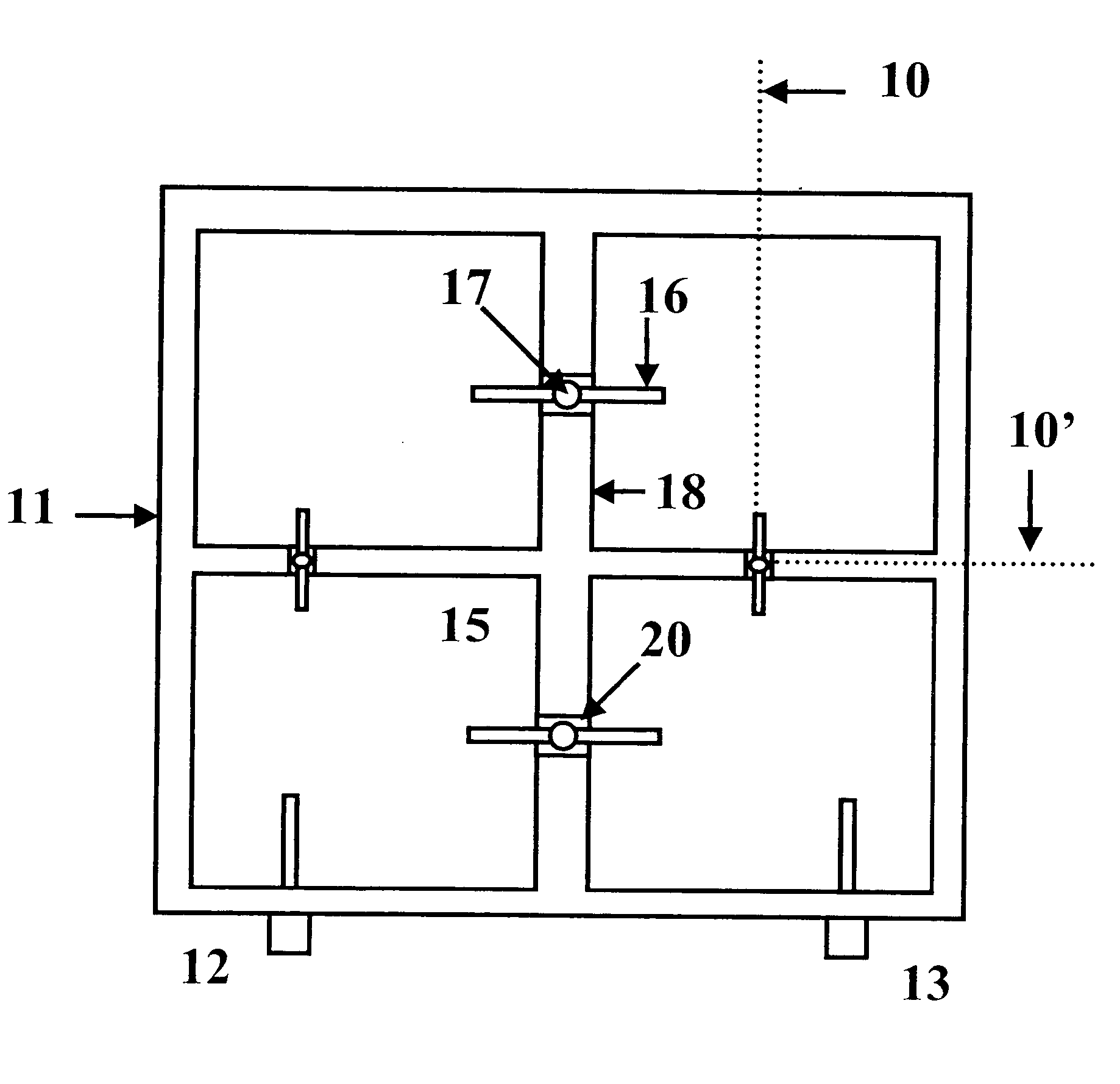
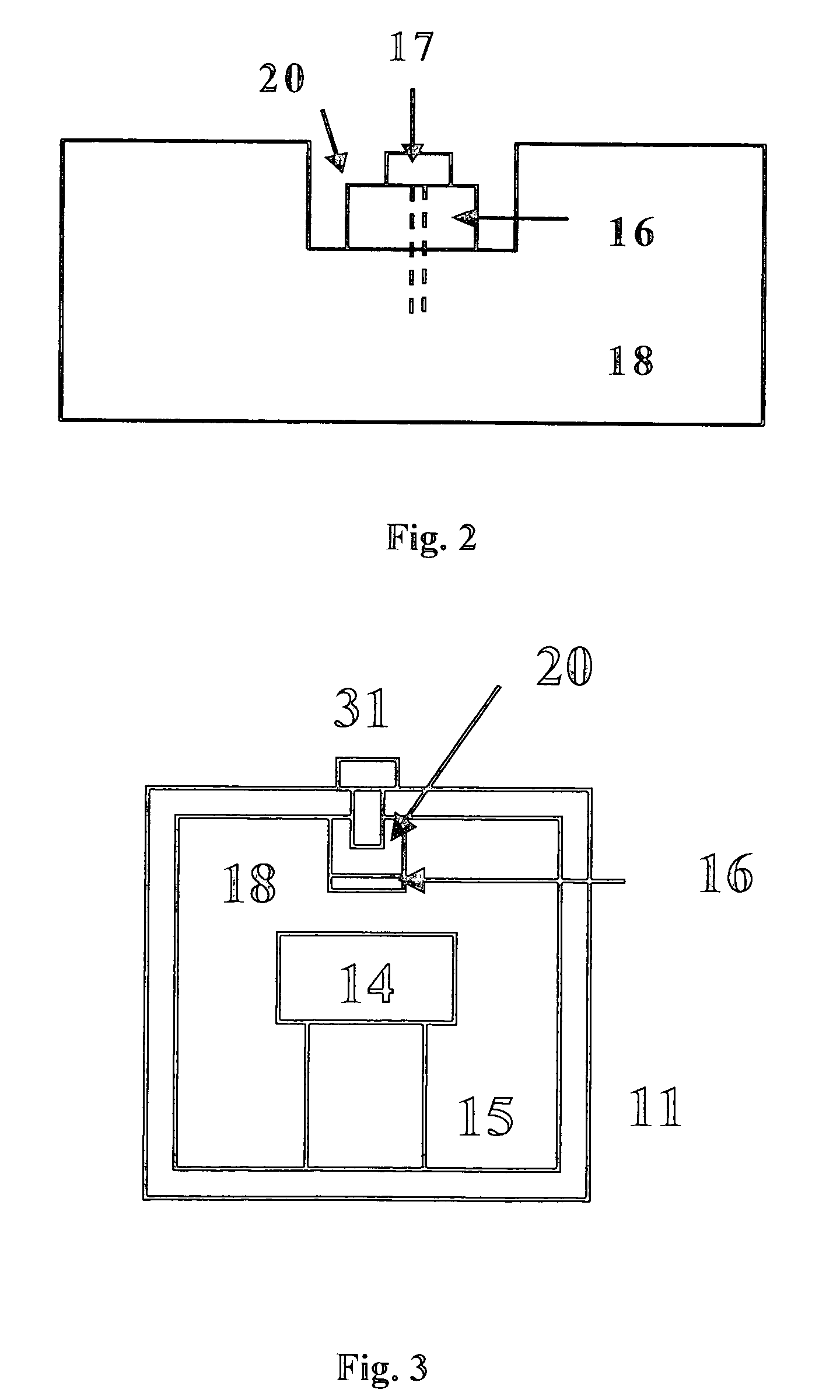
[0018] FIG. 1 illustrates an enclosure 11 of a direct coupled resonator filter which defines a plurality of resonant cavities 15. As illustrated in FIG. 3, each cavity 15 could contain a resonator 14, respectively. The resonator 14 can be dielectric, coaxial, or the like.

[0019] Turning now to FIG. 1, the filter further includes input and output devices 12 and 13 for receiving and transmitting an electromagnetic wave of greater power. The wave is filtered upon passing through the resonant cavities 15.

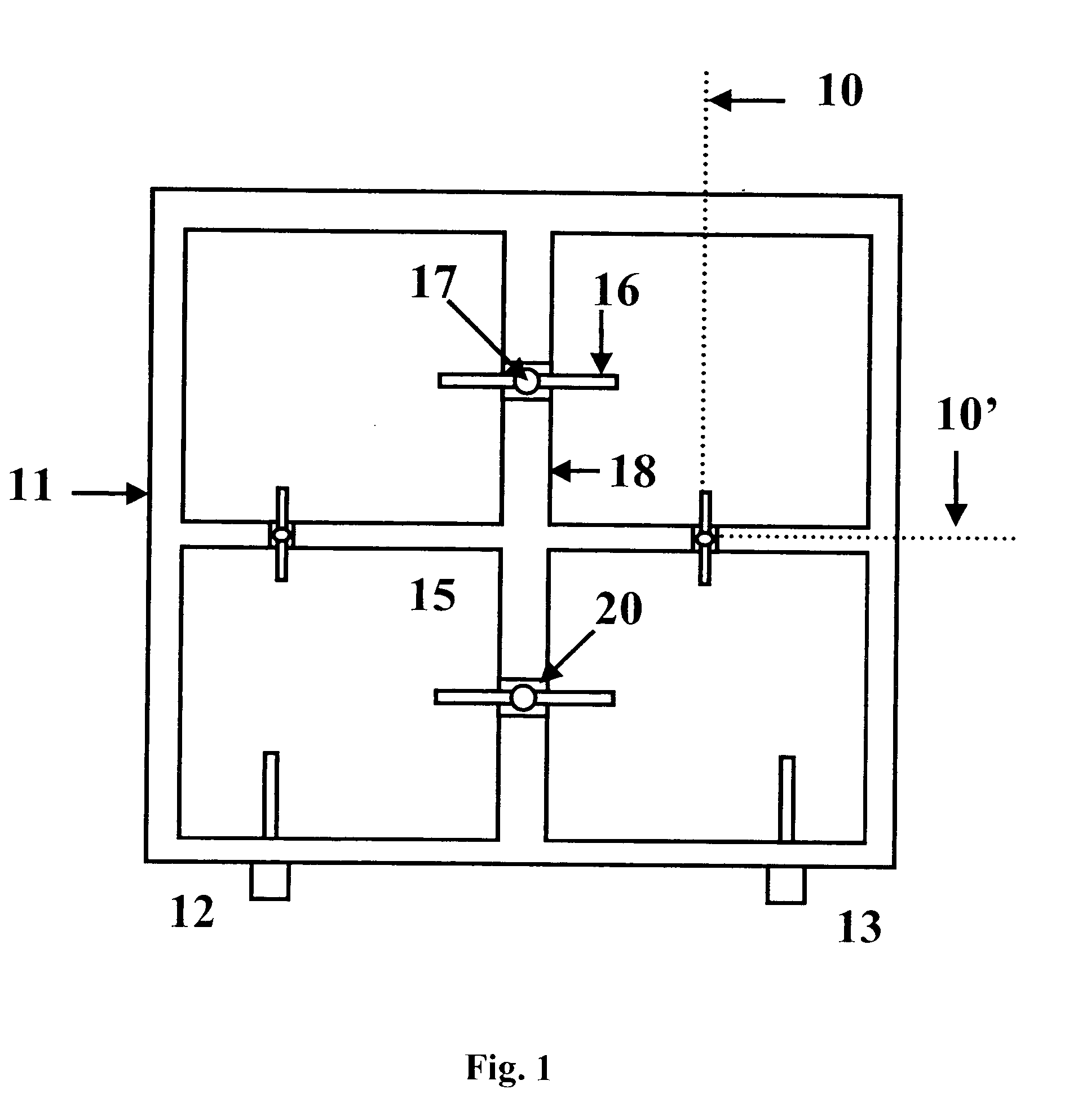
[0020] The enclosure 11 includes a peripheral outer wall surrounding the resonant cavities 15, such that an inner wall 18 is defined for separating two adjoining resonant cavities 15. A base wall of the housing defines the bottom of the filter housing 11. For example, an upper lid could cover the cavities 15, not shown for the sake of clarity. Input 12 and output 13 devices are provided and mounted on the same side of the housing 11. Note that they can be located in different sides of th...


PUM


Abstract

A direct coupled resonator filter having a plurality of resonant cavities (15) such that they are separated by means of inner (18) walls and a coupling (16) means couples two adjoining resonant cavities (15) since the coupling (169 means is located in a slot (20) defined in the inner (18) wall. Thus, a portion of an edge of the slot (20) comes into electric contact with the coupling (16) means. In general, this portion of the edge of the slot (20) corresponds to a horizontal edge surface of the inner (18) wall. It should be noted that the coupling (16) means is perpendicular to a vertical plane defined by the slot (20).

Description

OBJECT OF THE INVENTION[0001] The present invention relates to a direct coupled resonator filter that uses coupling devices to transmit a high electromagnetic wave from the filter input to the filter output through a plurality of resonator cavities.STATE OF THE ART[0002] A microwave resonator filter is known from Smith's U.S. Pat. No. 6,255,919 which describes a bandpass filter having an enclosure structure which defines four cavities. Each cavity contains a resonator, respectively. The filter includes input and output devices for receiving and transmitting an electromagnetic wave such as electromagnetic waves of high power. The wave is filtered upon passing through the resonators and the cavities. The resonators in the cavities are coupled through the use of a coupling structure which is located between the adjacent sequential cavities.[0003] Thus, the filter receives an electromagnetic wave through an input device which is coupled to the first resonator. The electromagnetic wave i...

Claims


Application Information

Patent Timeline
IPC IPC(8): H01P1/208
CPCH01P1/2084
Inventor CARPINTERO, ISIDRO HIDALGOPADILLA CRUZ, MANUEL JESUSGUIJARRO, RAFAEL TAPIA
Owner ALCATEL LUCENT SAS
Why Eureka
Try Eureka