Phantom for intensity modulated radiation therapy

a radiation therapy and intensity modulation technology, applied in the field of phantoms for dose characterization of imrt beams, can solve the problems of limited dose that can be given to the tumor, limited versatility of conventional phantoms, and inability to provide the flexibility of locating a radiation detector

Inactive Publication Date: 2004-11-18
UNIV OF TX MD ANDERSON CANCER CENT
View PDF6 Cites 61 Cited by
  • Summary
  • Abstract
  • Description
  • Claims
  • Application Information

AI Technical Summary

Problems solved by technology

The usual treatment field shape results in a three-dimensional treatment volume which includes segments of normal tissue, thereby limiting the dose that can be given to the tumor.
Conventional phantoms have limited versatility.
These designs do not provide the flexibility of locating a radiation detector for point dose verification at locations throughout the treatment field of the beam.

Method used


Image

  • Phantom for intensity modulated radiation therapy
  • Phantom for intensity modulated radiation therapy
  • Phantom for intensity modulated radiation therapy

Examples


Embodiment Construction

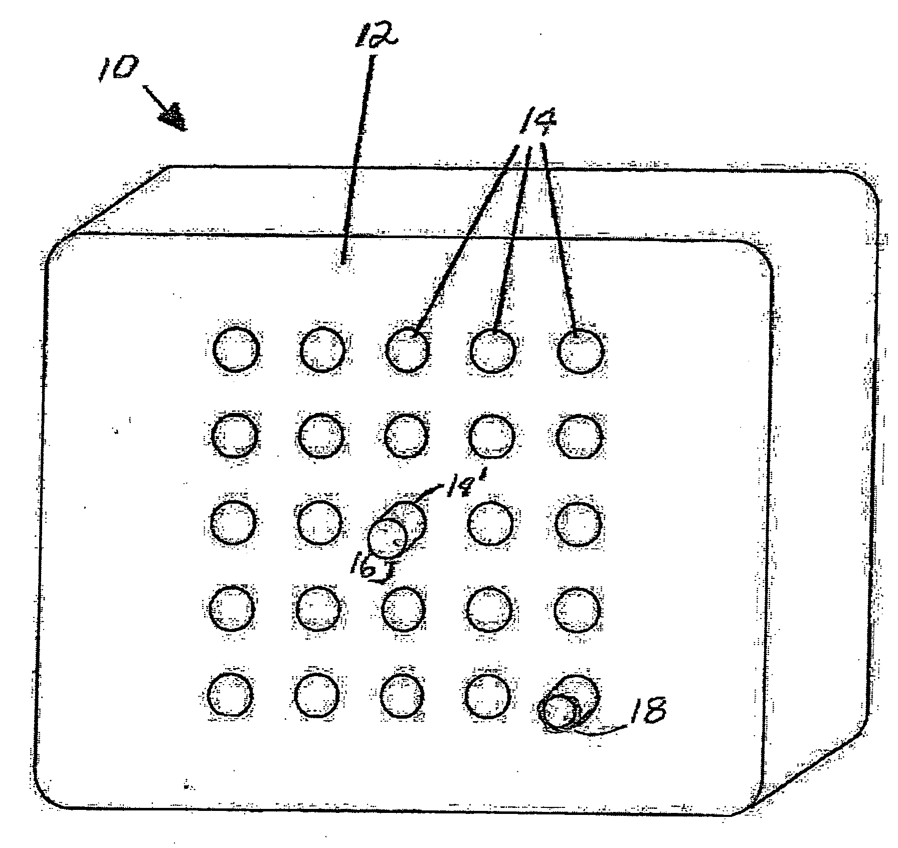
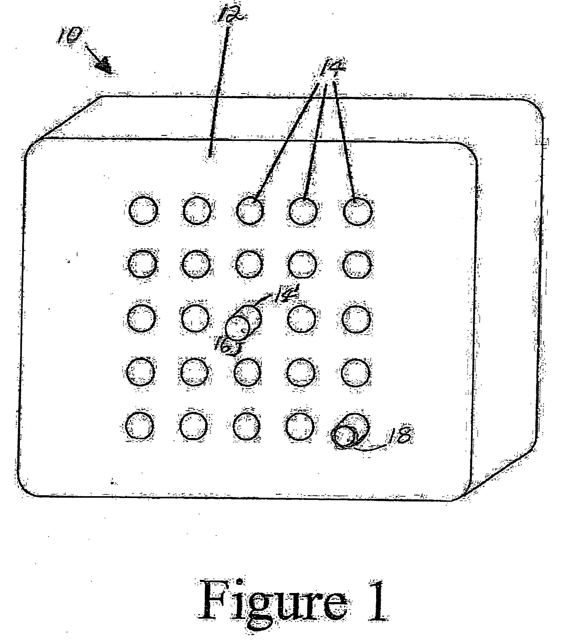
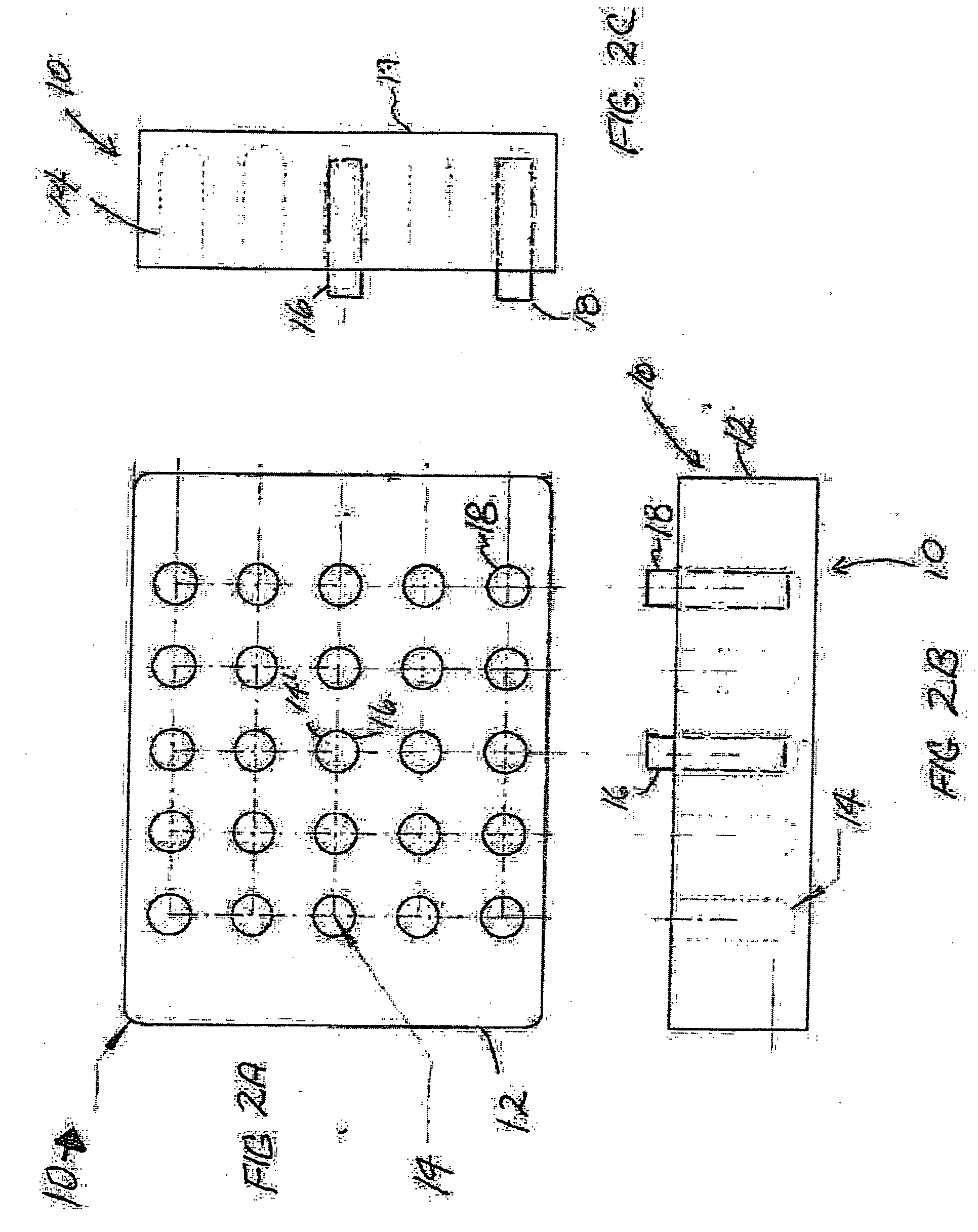
[0021] Referring now to the drawings, preferred embodiments of the invention will be described. In FIG. 1, there is shown a phantom 10 in accordance with the present invention. The phantom 10 includes a base 12, which contains a two-dimensional, rectangular array or matrix of cavities 14 formed in the base 12. Each cavity 14 is dimensioned and configured for having a radiation detector inserted therein. For the purposes of illustration, a single radiation detector 16, preferably in the form of an ion chamber, is shown inserted in the center cavity 14'. In a preferred embodiment, the two-dimensional array has an odd-by-odd number of cavities 14 so as to provide a central cavity 14'. Preferably, the cavities 14 do not extend all the way through the base 12 of the phantom 10. Although a ion chamber is the preferred radiation detector, those skilled in the art will recognized that other radiation detectors may be used with the present invention, such as solid state detectors, e.g., diod...


PUM


Abstract

Disclosed is a phantom for dose verification for intensity-modulated radiation therapy having a base of substantially tissue-equivalent material and a two-dimensional array of cavities formed in the base with each the cavities being configured and dimensioned to receive a radiation detector.

Description

[0001] 1. Field of the Invention[0002] This invention relates to a phantom for dose characterization of IMRT beams.[0003] 2. Description of Related Art[0004] Radiation therapy devices for the treatment of tumors in patients, using radiation emitting devices, are well known. A radiation therapy device generally includes a gantry which can be swiveled around a horizontal axis of rotation in the course of a therapeutic treatment. A linear accelerator is located within the gantry for generating a high energy radiation beam for therapy. This high energy radiation beam may be an electron beam or photon (x-ray) beam, for example. During treatment, the radiation beam is trained on a zone of a patient lying in the isocenter of the gantry rotation.[0005] In order to control the radiation emitted toward the patient, a beam shielding device, such as a plate arrangement or collimator, is typically provided in the trajectory of the radiation beam between the radiation source and the patient. The ...

Claims


Application Information

Patent Timeline
Patent Type & Authority Applications(United States)
IPC IPC(8): A61B6/00A61N5/10
CPCA61B6/583A61N5/1048A61N5/1075A61N2005/1076
Inventor RUSSELL, KEVIN J.
Owner UNIV OF TX MD ANDERSON CANCER CENT
Why Eureka
Try Eureka