Cage nut assembly having stand-offs
- Summary
- Abstract
- Description
- Claims
- Application Information
AI Technical Summary
Benefits of technology
Problems solved by technology
Method used
Image

Examples
first embodiment
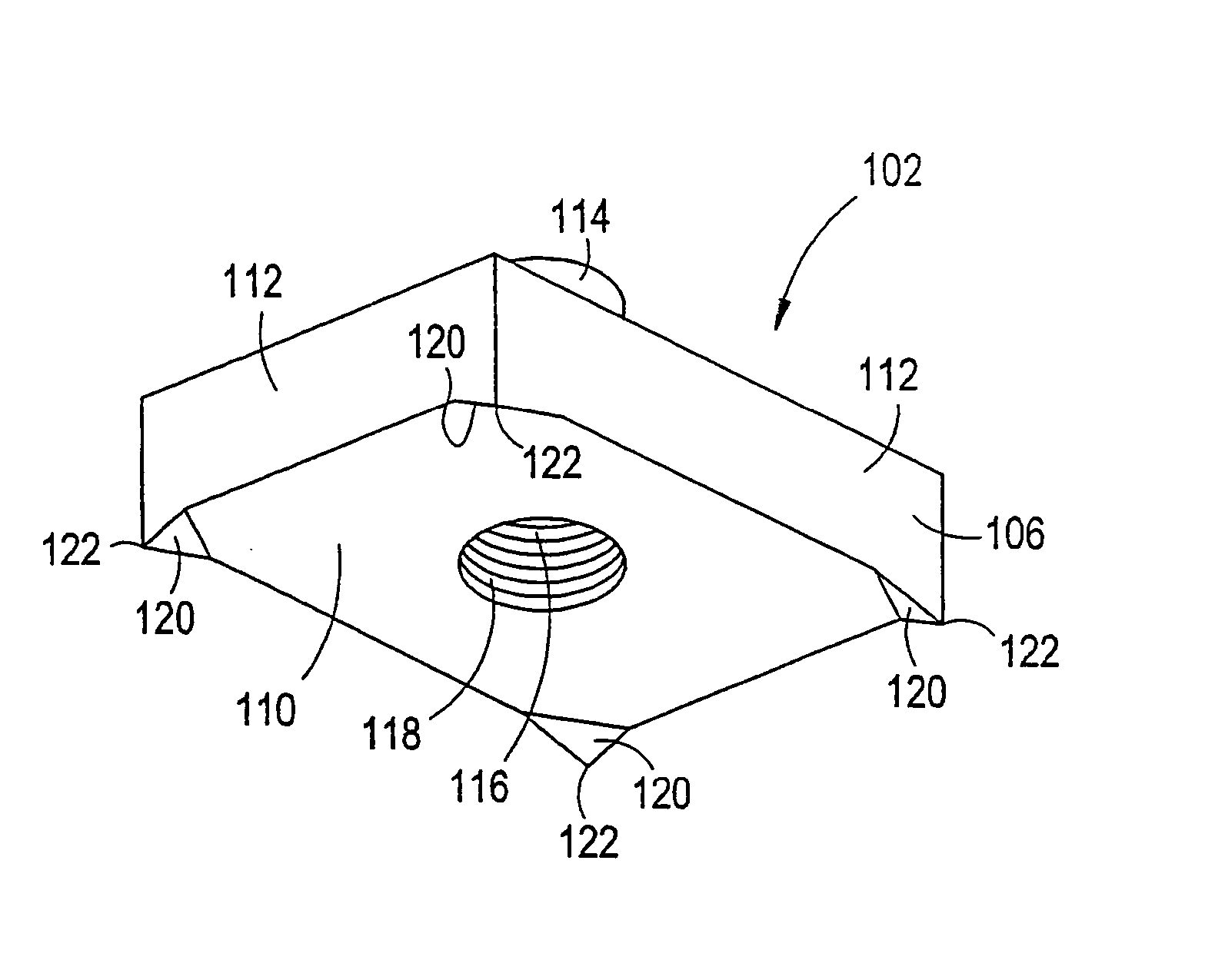
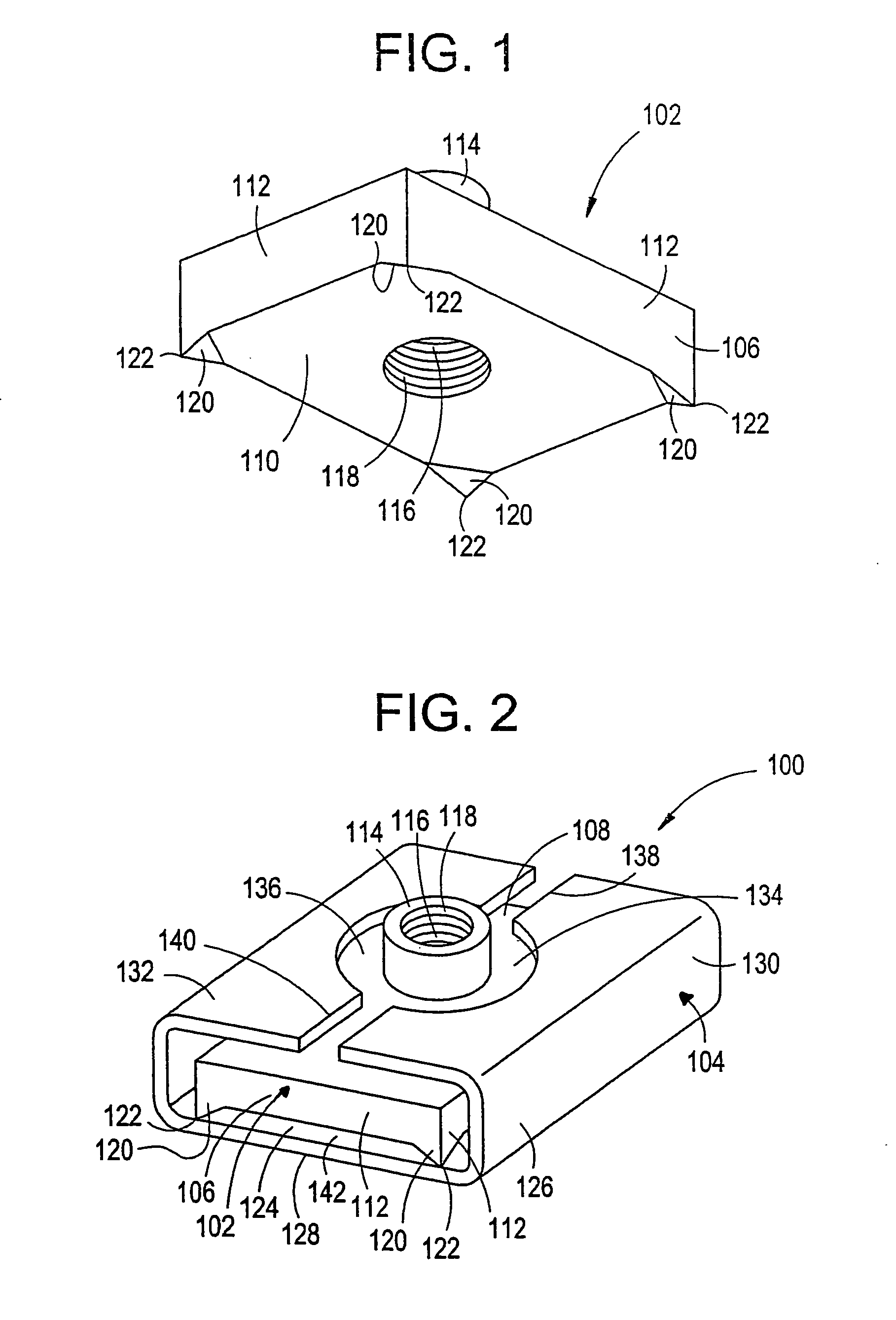
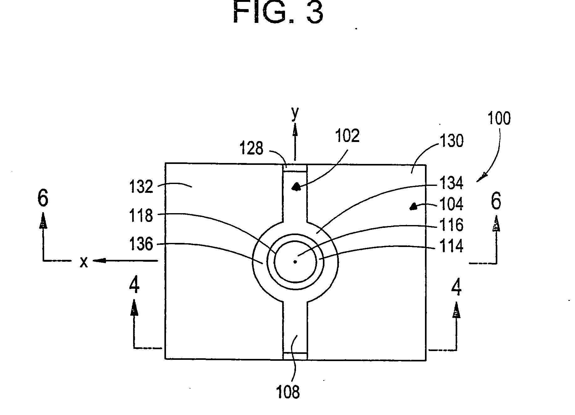
[0091] Attention is directed to a cage nut assembly 100 of the present invention, which is best illustrated in FIGS. 1-6. The cage nut assembly 100 includes a nut 102 and a cage 104.
[0092] The nut 102 is best illustrated in FIG. 1 and includes a rectangular plate 106 having a generally planar upper surface 108, a generally planar lower surface 110 and sidewalls 112 which connect the upper and lower surfaces 108, 110. The nut 102 also includes a cylindrical member 114 which extends outwardly from the upper surface 108 of the nut 102. The cylindrical member 114 is preferably in the form of a right circular cylinder. An aperture 116 extends through the nut member 102 from the plate 106 into the cylindrical member 114. The aperture 116 may be closed at the lower surface 110 of the plate 106 or it may extend all the way through the plate 106. The aperture 116 defines an aperture wall 118 which is preferably threaded and is capable of receiving a bolt or screw 160 to be attached thereto.
[...
second embodiment
[0102] Attention is directed to a cage nut assembly 200 of the present invention, which is best illustrated in FIGS. 7-12. The cage nut assembly 200 includes a nut 202 and a cage 204.
[0103] The nut 202 is best illustrated in FIG. 7 and includes a rectangular plate 206 having a generally planar upper surface 208, a generally planar lower surface 210 and sidewalls 212 which connect the upper and lower surfaces 208, 210. The nut 202 also includes a cylindrical member 214 which extends outwardly from the upper surface 208 of the nut 202. The cylindrical member 214 is preferably in the form of a right circular cylinder. An aperture 216 extends through the nut member 202 from the plate 206 into the cylindrical member 214. The aperture 216 may be closed at the lower surface 210 of the plate 206 or it may extend all the way through the plate 206. The aperture 216 defines an aperture wall 218 which is preferably threaded and is capable of receiving a bolt or screw 260 to be attached thereto....
third embodiment
[0115] Attention is directed to a cage nut assembly 300 of the present invention, which is best illustrated in FIGS. 13-17. The cage nut assembly 300 includes a nut 302 and a cage 304.
[0116] The nut 302 is best illustrated in FIG. 13 and includes a rectangular plate 306 having a generally planar upper surface 308, a generally planar lower surface 310 and sidewalls 312 which connect the upper and lower surfaces 308, 310. The nut 302 also includes a cylindrical member 314 which extends outwardly from the upper surface 308 of the nut 302. The cylindrical member 314 is preferably in the form of a right circular cylinder. An aperture 316 extends through the nut member 302 from the plate 306 into the cylindrical member 314. The aperture 316 may be closed at the lower surface 310 of the plate 306 or it may extend all the way through the plate 306. The aperture 316 defines an aperture wall 318 which is preferably threaded and is capable of receiving a bolt or screw (not shown) to be attache...
PUM
 Abstract
Description
Claims
Application Information
 - Generate Ideas
- Intellectual Property
- Life Sciences
- Materials
- Tech Scout
- Unparalleled Data Quality
- Higher Quality Content
- 60% Fewer Hallucinations
Browse by: Latest US Patents, China's latest patents, Technical Efficacy Thesaurus, Application Domain, Technology Topic, Popular Technical Reports.
© 2025 PatSnap. All rights reserved.Legal|Privacy policy|Modern Slavery Act Transparency Statement|Sitemap|About US| Contact US: help@patsnap.com