
Method and system of fault patterns oriented defect diagnosis for memories

a memory and fault pattern technology, applied in the field of memory fault pattern oriented defect diagnosis, can solve the problems of low yield, memory test becomes more difficult and complicated, memory diagnosis and failure analysis (fa) become critical issues,

Inactive Publication Date: 2004-11-25
SPIROX INC +1
View PDF4 Cites 9 Cited by
  • Summary
  • Abstract
  • Description
  • Claims
  • Application Information

AI Technical Summary

Benefits of technology

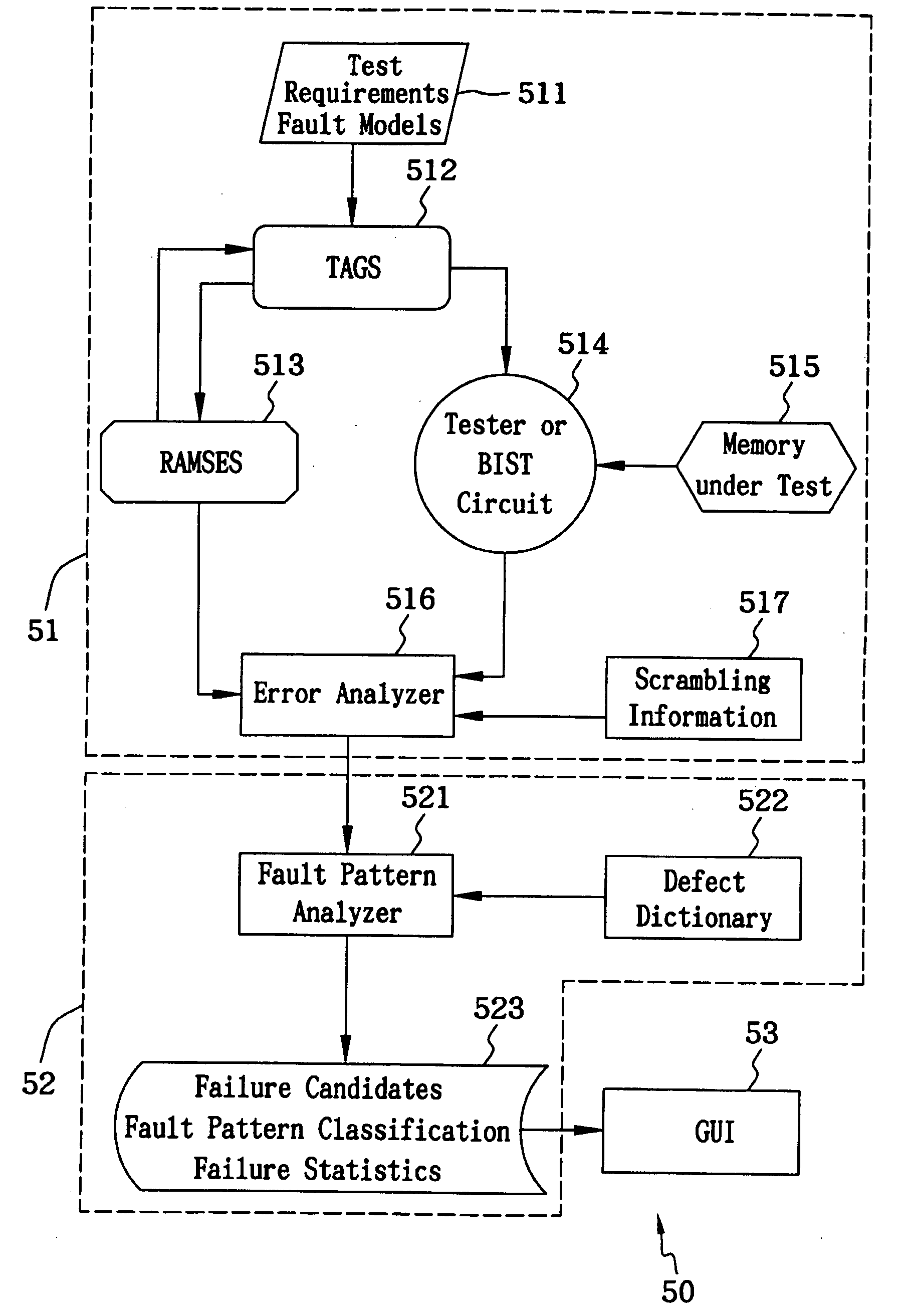
[0012] The second objective of the invention is to provide a method and system of defect diagnosis for improving the yield of memories. Circuit designers and product engineers can easily discriminate the real root causes of memory failures by means of this method, so they can effectively improve the yield.
[0013] In order to achieve these objectives, the present invention discloses a method and system of fault patterns oriented defect diagnosis for memories that can analyze and recognize fault patterns and failure patterns after Memory Error Catches and Analyses (MECA) are done. The existent fault patterns are compared with a pre-simulated and grouped defect dictionary that defines possible defects of different fault patterns, and the defects of memories caused from their manufacturing process or circuit layout can be detected. This method also employs a graphic user interface (GUI) to display and designate memory cells where defects exist as fault models and fault patterns, thus the circuit designers and product engineers can easily discriminate the real root causes of memory failures.

Problems solved by technology

Since the capacity and density of the embedded memories are dramatically increased, memory tests become more difficult and complicated.
In order to improve the yield of the SoC devices, the memory diagnosis and failure analysis (FA) become critical issues.
Because defects occurring in the manufacturing process of a wafer usually result in a low yield, the FA can detect the root causes of the low yield.
However, the conventional FA is not applicable to defect-level tests or memory diagnoses due to the lack of adequate methods and tools when the process technology enters the deep sub-micro era.
Yet, it is difficult for most inexperienced engineers or even some experienced engineers to find the root causes to improve the yield.
Nevertheless, both failure patterns and failure bitmaps have many disadvantages; for example, various root causes are referred to the same failure pattern so as to have an inaccurate diagnostic result.
On the other hand, fault models are not enough for test algorithms to detect all possible defects although new fault models are continuously developed.

Method used


Image

  • Method and system of fault patterns oriented defect diagnosis for memories
  • Method and system of fault patterns oriented defect diagnosis for memories
  • Method and system of fault patterns oriented defect diagnosis for memories

Examples


Embodiment Construction

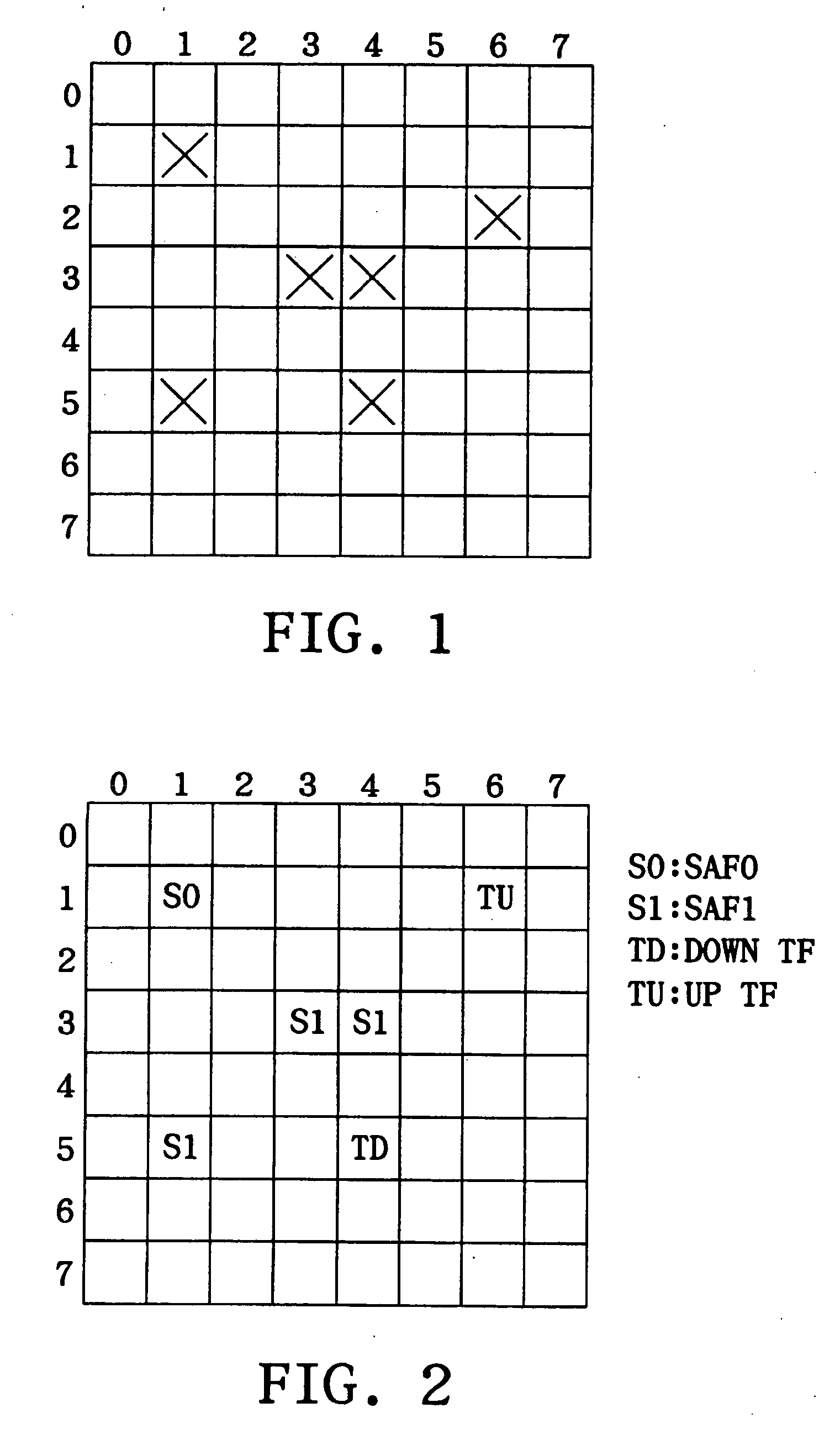
[0021] Generally speaking, adequate fault models are selected as error detectable orientations before a test algorithm is executed. The fault models for memory tests usually include SAF (stuck-at fault), TF (transition fault), SOF (stuck-open fault), AF (address decoder fault), CF (coupling fault) and RDF (read disturb fault). Defects of memories can be detected through the fault models, and the root causes of the defects are to be analyzed further.

[0022] Among numerous test algorithms, the one based on a March algorithm can more easily have practical applications not only for automatic test equipment (ATE) but also for SoC devices with built-in self-test circuits. The following expression is a March 17N diagnostic algorithm in accordance with the embodiment of the present invention.

(w0)(r0,w1,r1)(r1,w0,r0)(r0,w1)(r1,w0

[0023] wherein the symbol indicates address increment, the symbol indicates address decrement, the characters r and w in these brackets respectively represent read an...


PUM


Abstract

A method and system of fault patterns oriented defect diagnosis for memories can analyze and recognize fault patterns and failure patterns after Memory Error Catches and Analyses (MECA) are done. The existent fault patterns are compared with a pre-simulated and grouped defect dictionary that defines possible defects of different fault patterns, and the defects of memories caused from their manufacturing process or circuit layout can be detected.

Description

[0001] 1. Field of the Invention[0002] The present invention relates to a method and system of defect diagnosis for memories, and more particularly to a method and system of memory defect diagnosis oriented by fault patterns.[0003] 2. Description of the Related Art[0004] Memories are basic components applied to general digital systems, and occupy most of a system-on-chip (SoC) area on an embedded design; hence they can usually determine whether or not the yield of the SoC devices is high. Since the capacity and density of the embedded memories are dramatically increased, memory tests become more difficult and complicated. In order to improve the yield of the SoC devices, the memory diagnosis and failure analysis (FA) become critical issues.[0005] Because defects occurring in the manufacturing process of a wafer usually result in a low yield, the FA can detect the root causes of the low yield. According to the result of the FA, IC design engineers can decide how to improve the manufa...

Claims


Application Information

Patent Timeline
IPC IPC(8): G11C29/56
CPCG11C29/56G11C2029/5606G11C2029/5604
Inventor WU, CHENG-WENHUANG, CHIH-TSUNWANG, CHIH-WEACHENG, KUO-LIANGLEE, JIH-NUNG
Owner SPIROX INC
Learn More