Magnetic coupling pump

a technology of coupling pump and magnetism, which is applied in the direction of pump components, piston pumps, non-positive displacement fluid engines, etc., can solve the problems of further extending the life of the pump, and no means of cooling down a part inward of the stator

Inactive Publication Date: 2004-11-25
AISAN IND S
View PDF4 Cites 68 Cited by
  • Summary
  • Abstract
  • Description
  • Claims
  • Application Information

AI Technical Summary

Problems solved by technology

In the conventional outer-rotor type magnetic coupling pump, however, there is no means of cooling down a part inward of the stator though the outer circumference of the stator can be cooled down by coolant interposed between the stator and the magnet section.
Consequently, burnout of the coils of the stator and heat deformation of the housing are properly prevented, which further elongates a life span of the pump even under high-load driving which consumes a lot of electricity.

Method used


Image

  • Magnetic coupling pump
  • Magnetic coupling pump
  • Magnetic coupling pump

Examples


Embodiment Construction

[0020] Preferred embodiments of the present invention are now described below with reference to the accompanying drawings. However, the invention is not limited to the embodiments disclosed herein. All modifications within the appended claims and equivalents relative thereto are intended to be encompassed in the scope of the claims.

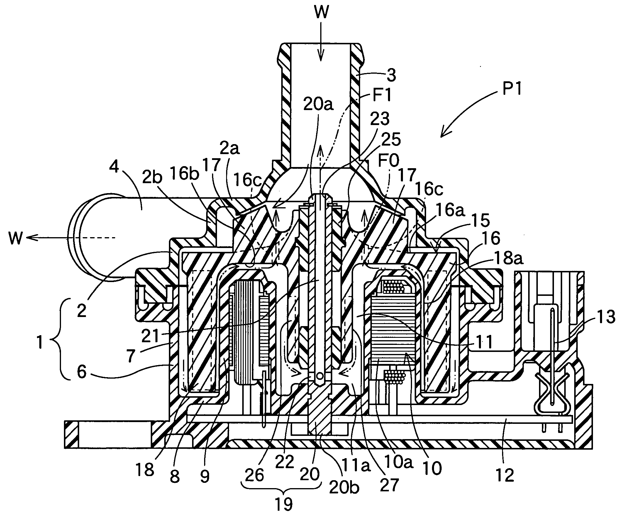
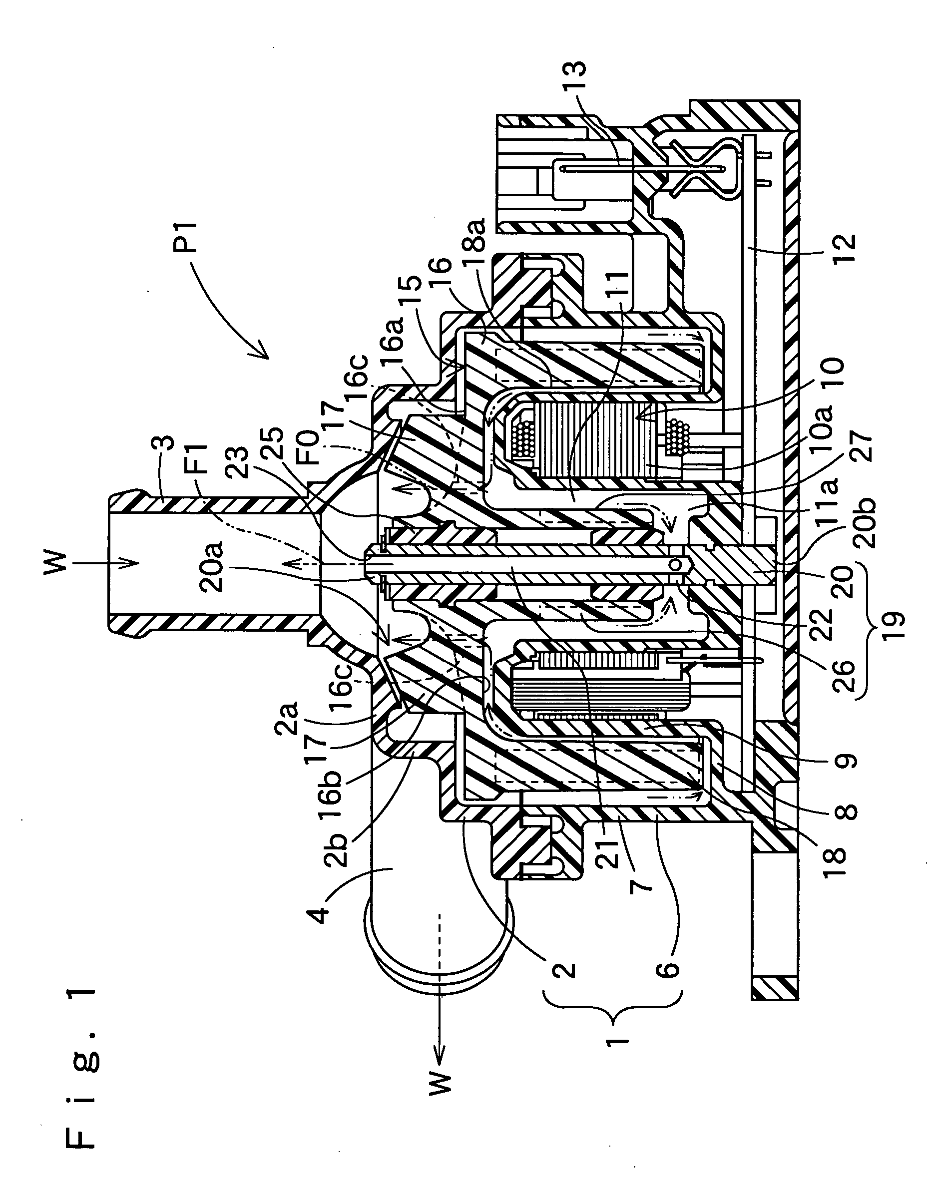
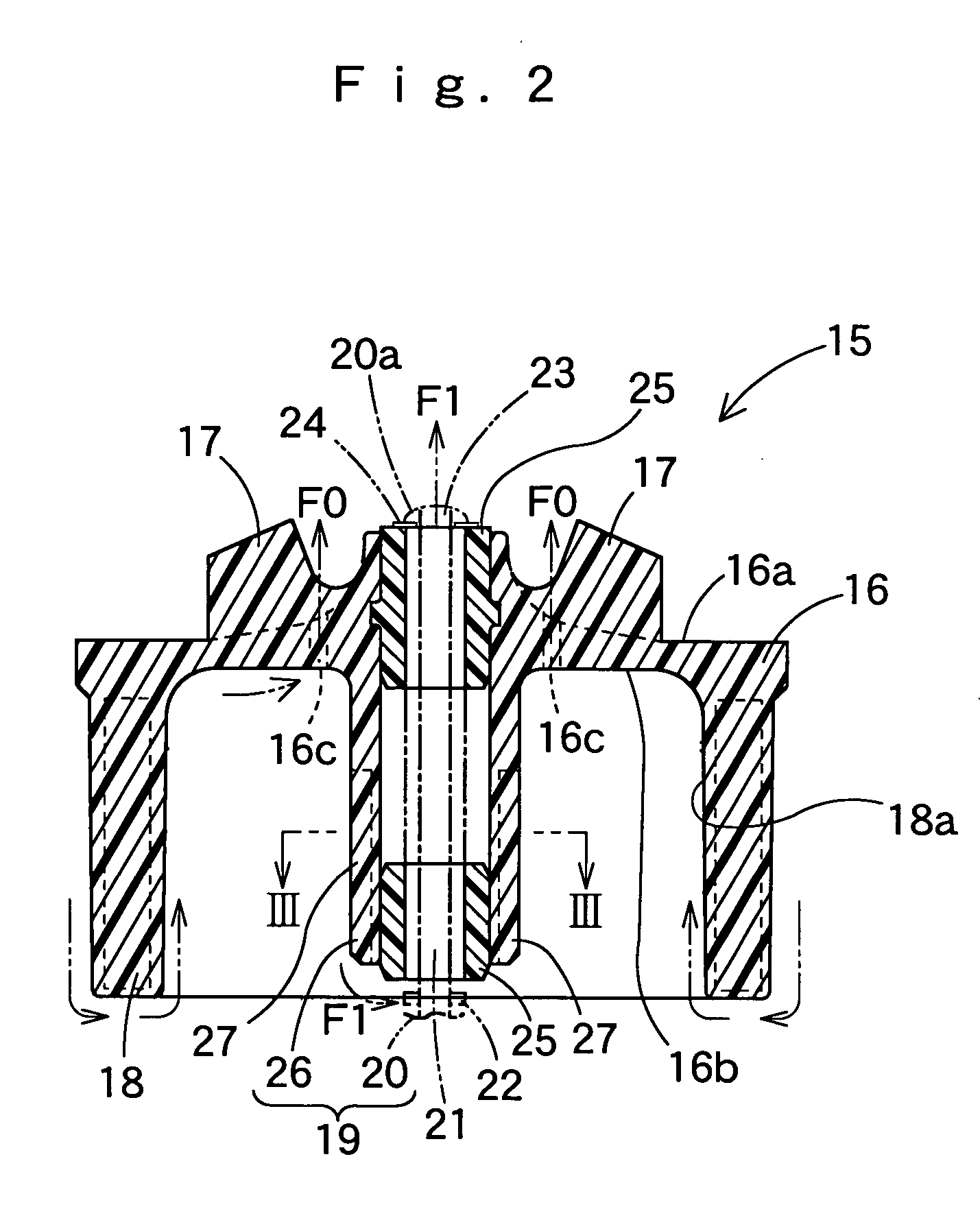
[0021] FIGS. 1 to 3 illustrate an embodiment P1 of the magnetic coupling pump according to the present invention for feeding engine coolant W for vehicles. The pump P1 includes a housing 1 which is made from synthetic resin and has therein a rotor 15 with a plurality of impellers 17 for feeding the coolant W.

[0022] The housing 1 includes a pump chamber 2 in which the impellers 17 of the rotor 15 are located, and a motor chamber 6 located below the pump chamber 2. The pump chamber 2 has a ceiling wall 2a and has a substantially cylindrical shape. An inlet pipe 3 for introducing the coolant W projects upward from the ceiling wall 2a, and an outlet pipe 4 fo...


PUM


Abstract

A magnetic coupling pump according to the present invention has a housing including a pump chamber a motor chamber. The rotor includes a plurality of impellers projected from top face of a substantially disc-shaped main body of the rotor to be located in the pump chamber, and a substantially cylindrical magnet section projected from back face of the main body to be located in the motor chamber. The rotor is located in engine coolant, and is driven by a stator located inward of the magnet section in the motor chamber for sucking coolant from an inlet port and exhausting it from an outlet port. The pump is provided along an inner circumference of the stator with a cavity communicating with passages of fluid along an inner circumference of the magnet section and the back face of the main body of the magnet section. The cavity admits the coolant. The pump according to the present invention is able to prevent heat-up in the inner circumferential part of the stator.

Description

[0001] The present application claims priority from Japanese Patent Application No. 2003-142389 of Hatano, filed on May 20, 2003, the entirety of which is hereby incorporated into the present application by reference.[0002] 1. Field of the Invention[0003] The present invention relates to a magnetic coupling pump for pumping fluids such as engine coolant for vehicles, and more particularly, relates to an outer-rotor type magnetic coupling pump in which a stator is located toward a rotation center of a rotor having impellers for feeding fluids, and a substantially cylindrical magnet section of the rotor is located around the stator.[0004] 2. Description of the Related Art[0005] In conventional outer-rotor type magnetic coupling pumps for engine coolant for vehicles, a rotor having impellers for feeding coolant is located in a housing, as disclosed in Japanese Laid Open Patent Application No. JP10-311290.[0006] In this magnetic coupling pump, the housing includes a pump chamber having ...

Claims


Application Information

Patent Timeline
Patent Type & Authority Applications(United States)
IPC IPC(8): F04D13/02F04D13/06F04D29/58
CPCF04D29/588F04D13/064F04D13/0673F04D29/5806
Inventor HATANO, MAKOTO
Owner AISAN IND S
Why Eureka
Try Eureka