
Flapper valve for a toilet tank

Inactive Publication Date: 2004-12-02
SHIH CHUNG CHEN
View PDF0 Cites 5 Cited by
  • Summary
  • Abstract
  • Description
  • Claims
  • Application Information

AI Technical Summary

Benefits of technology

[0020] In such an arrangement, wheel the flapper valve (10) is rotated to open the top opening of the drain pipe, the water in the tank will enter the chamber (131) through the opening (132) and the air in the chamber (131) will be discharged through the passage (21) of the control member (20). Because the air is discharged via a way different from that for water entering the chamber (131) the speed for discharging the air out from the chamber (131) is increased. Time for discharging the air is also reduced. Consequently, the flapper vale (10) will drop and seal the top opening of the drain before the tank can be flushed out empty. This can reduce the volume of flushing water of the toilet tank, and the waste of water is prevented.

Problems solved by technology

However, because the air in the chamber is discharged via the bottom opening in the cone (62) from where the water in the tank enters the chamber, to discharge the air from the chamber via the bottom opening take a long time, and the tank is always completely emptied.
The volume of flushing water of a toilet tank with a conventional flapper valve (60) is too large and thus is wasteful.

Method used


Image

  • Flapper valve for a toilet tank
  • Flapper valve for a toilet tank
  • Flapper valve for a toilet tank

Examples


first embodiment

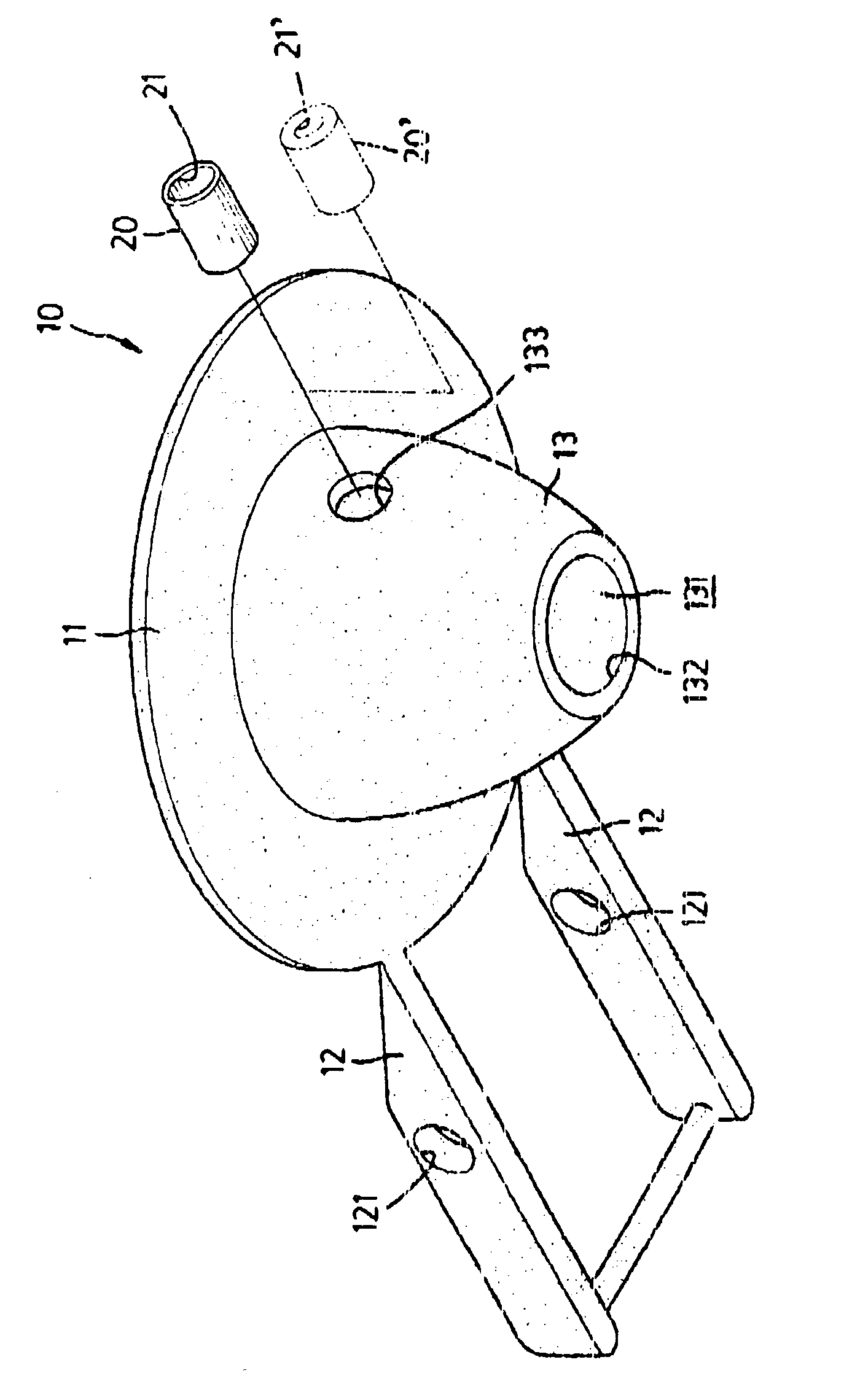
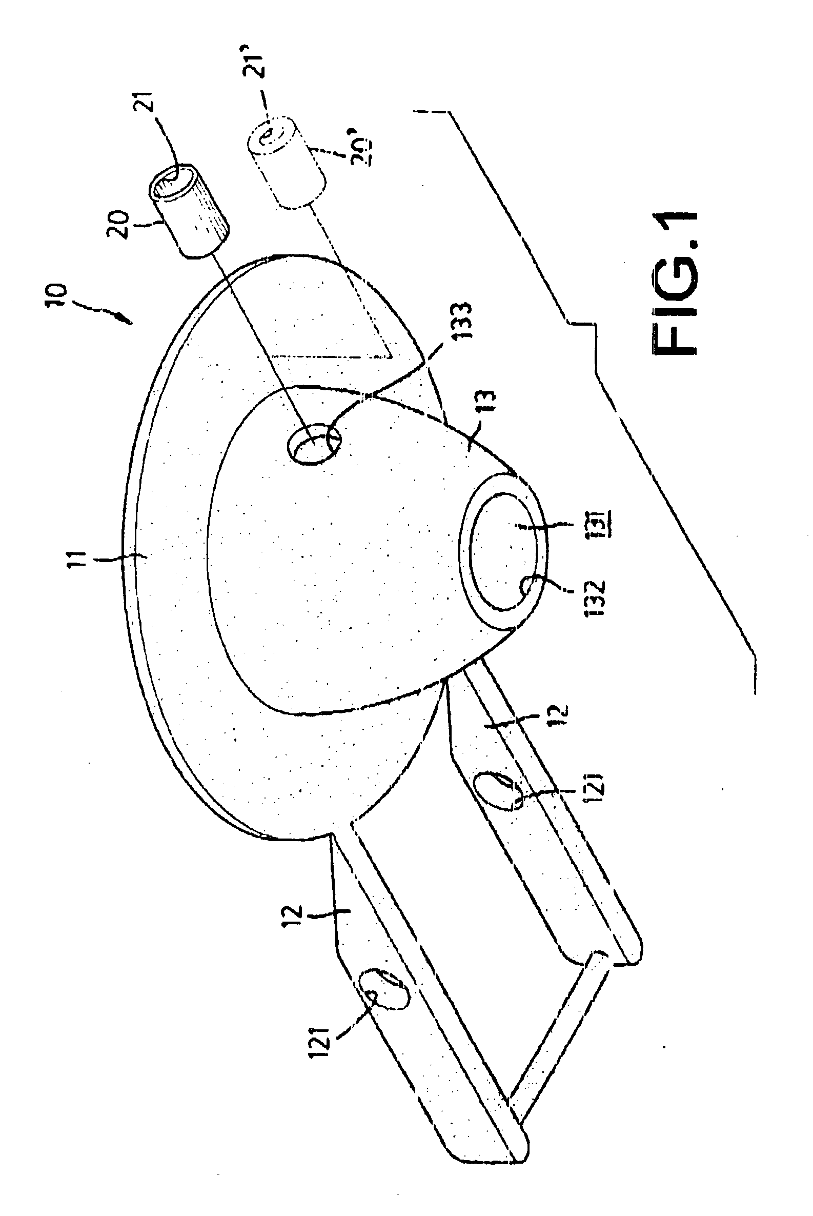
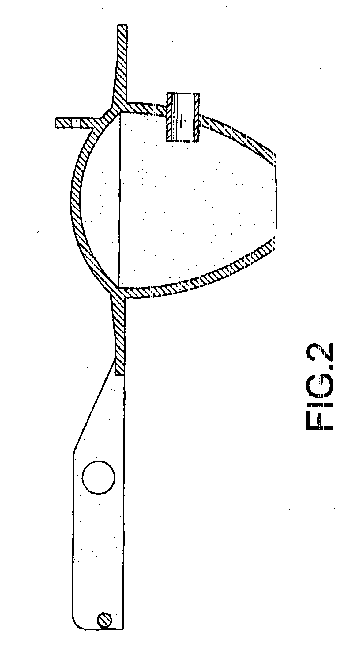
[0017] With reference to FIGS. 1 and 2, a flapper valve (10) in accordance with the present invention for a toilet tank comprises an annular flange (11), a cone (13) and an airflow controlling member (20). The annular flange (11) is pivotally connected to in overflow pipe (not shown) in the toilet tank and closes a top opening of a drain pipe (not shown) in the toilet. In practice two arms (12) extend from the flange (11) in parallel, and each arm (12) has a mounting hole (121) to pivotally receive a stub (not shown) mounted on the overflow pipe. With the engagements of the mounting holes (121) in the arms (12) and the stubs on the overflow pipe, the annular flange (11) is pivotally connected to the overflow pipe.

[0018] The cone (13) is hollow and protrudes from the bottom of the annular flange (11). The cone (13) has a chamber (131) and an opening (132) defined in the bottom of the cone (13) and communicating with the chamber (131). A vent (133) is defined in the periphery of the c...

third embodiment

[0024] With reference to FIGS. 5 and 6, the airflow controlling member (40) comprises a plug (41) and a disk (42). The plug (41) is received in the vent (133). A bore (411) is defined in the plug (41), and a ventage (412) is defined through the plug (41) and communicates with the chamber (131) in the cone (13). The disk (42) is moveably mounted on the plug (41) and corresponds to the ventage (412) in the plug (41). A shaft (421) protrudes from the disk (42) and is moveably inserted into the bore (411) in the plug (41) so as to moveably combine the disk (42) with the plug (41). A gap (not numbered) is defined between the plug (41) and the disk (42).

[0025] In such an embodiment, the air in the chamber (131) can be discharged from the ventage (412) in the plug (41) and the gap between the plug (41) and the disk (42). When the disk (42) is moved relative to the plug (41) the gap between the plug (41) and the disk (42) is changed. Accordingly, the discharging rate of the air is adjustabl...


PUM


Abstract

A flapper valve for a toilet tank has an annular flange, a cone and an airflow controlling member. The cone is hollow and protrudes from the bottom of the annular flange. The cone has chamber and a vent defined in the outer periphery of the cone and communicating with the chamber. The airflow controlling member is attached to the cone and corresponds to the vent to make air in the chamber being discharged through the airflow controlling chamber. Accordingly, the discharging rate of the air from the chamber in the cone is adjustable, and the volume of flushing water of the toilet is also adjustable.

Description

[0001] 1. Field of the Invention[0002] The present invention relates to a flapper valve, and more particularly to a flapper valve for a toilet tank and having airflow controlling member to adjust the volume of flushing water of a toilet tank.[0003] 2. Description of Related Art[0004] With reference to FIG. 7, a flapper valve (60) is pivotally connected to an overflow pipe (51) in a toilet tank to close a drain pipe (50) of the toilet tank. The flapper valve (60) is connected via a chain to a handle (not shown) protruding from the toilet tank. When the handle is pressed, the flapper valve (60) will be pivotally rotated relative to the overflow pipe (51) to open the drain pipe (50). Accordingly, the water stored in the tank will be drained into the bowl of the toilet through the drain pipe (50). The conventional flapper valve (60) in accordance with the prior art comprises an annular flange (61) and a cone (62). The flange (61) is pivotally connected to two stubs (52) on the overflow ...

Claims


Application Information

Patent Timeline
IPC IPC(8): E03D1/14E03D1/30
CPCE03D1/14E03D1/306
Inventor SHIH, CHUNG-CHEN
Owner SHIH CHUNG CHEN
Learn More