Phev (pneumatic hybrid electric vehicle)

a hybrid electric vehicle and pneumatic technology, applied in the direction of machines/engines, electric devices, combination engines, etc., can solve the problems of large start power capacity of vehicles, low energy efficiency and noxious fumes,

Inactive Publication Date: 2004-12-02
PARKER INTANGIBLES LLC +1
View PDF8 Cites 31 Cited by
  • Summary
  • Abstract
  • Description
  • Claims
  • Application Information

AI Technical Summary

Problems solved by technology

However, since the steam locomotives or steam ships using such a steam engine use a coal for fuel, the energy efficiency is very low while emitting noxious fumes.
However, a vehicle provided with the engine using electricity has a problem in being commercialized due to the following reasons.
That is, the vehicle requires a large capacity of start power during the

Method used


Image

  • Phev (pneumatic hybrid electric vehicle)
  • Phev (pneumatic hybrid electric vehicle)
  • Phev (pneumatic hybrid electric vehicle)

Examples


Embodiment Construction

[0024] Preferred embodiments of the present invention will be described more in detail in conjunction with the accompanying drawings.

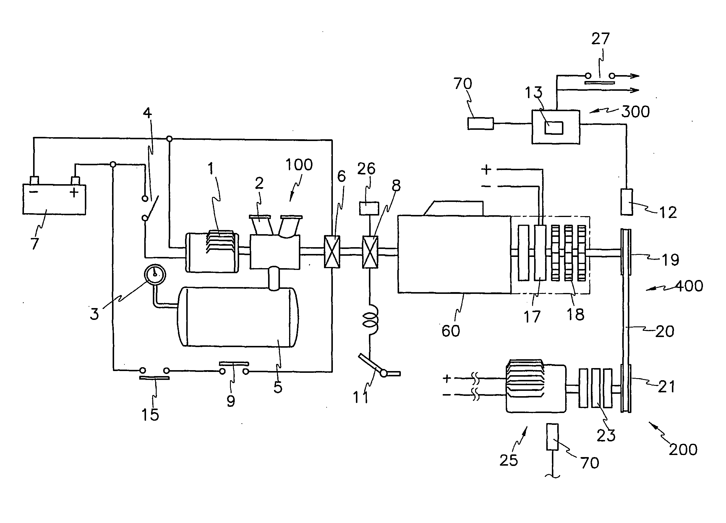
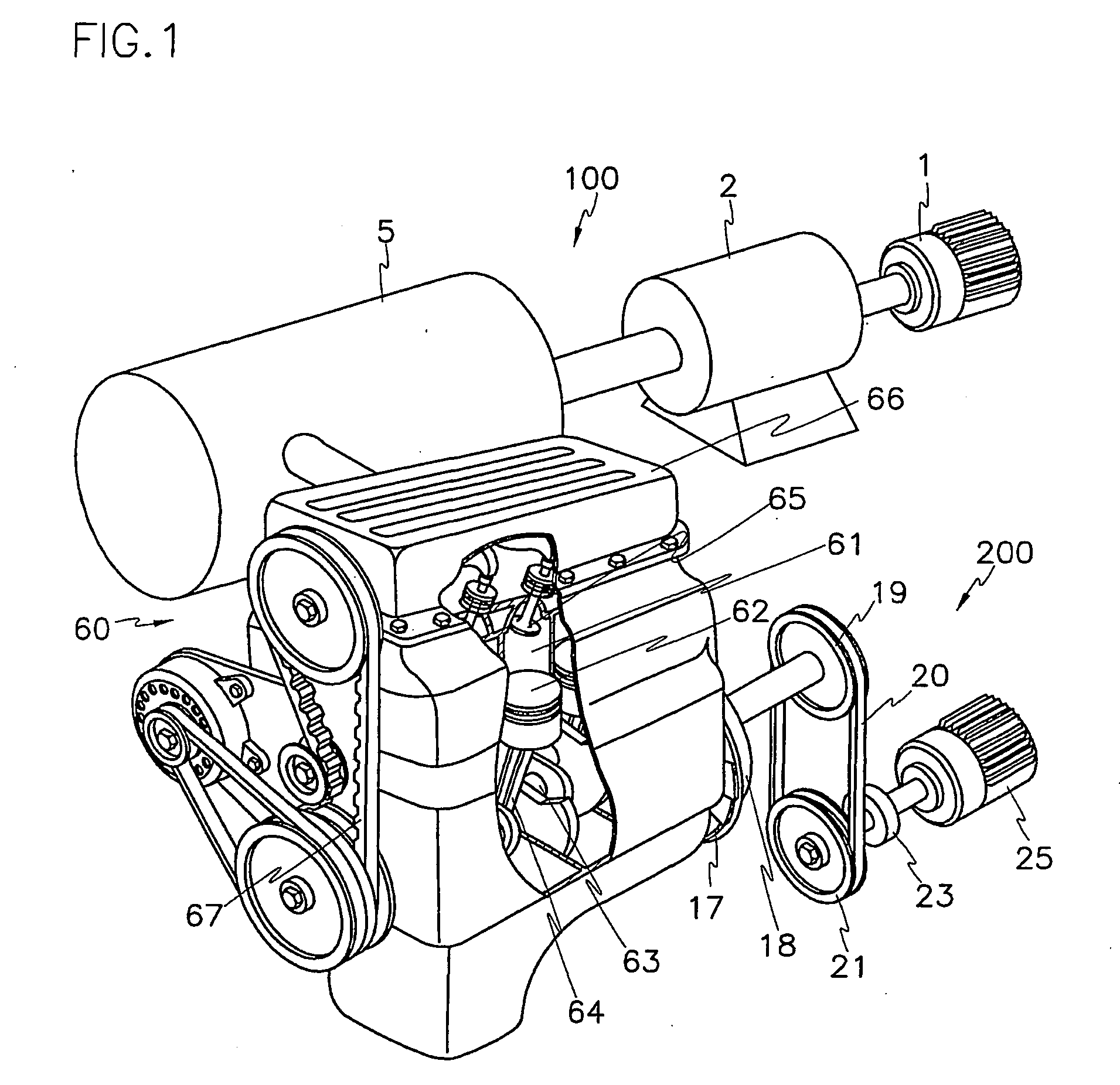
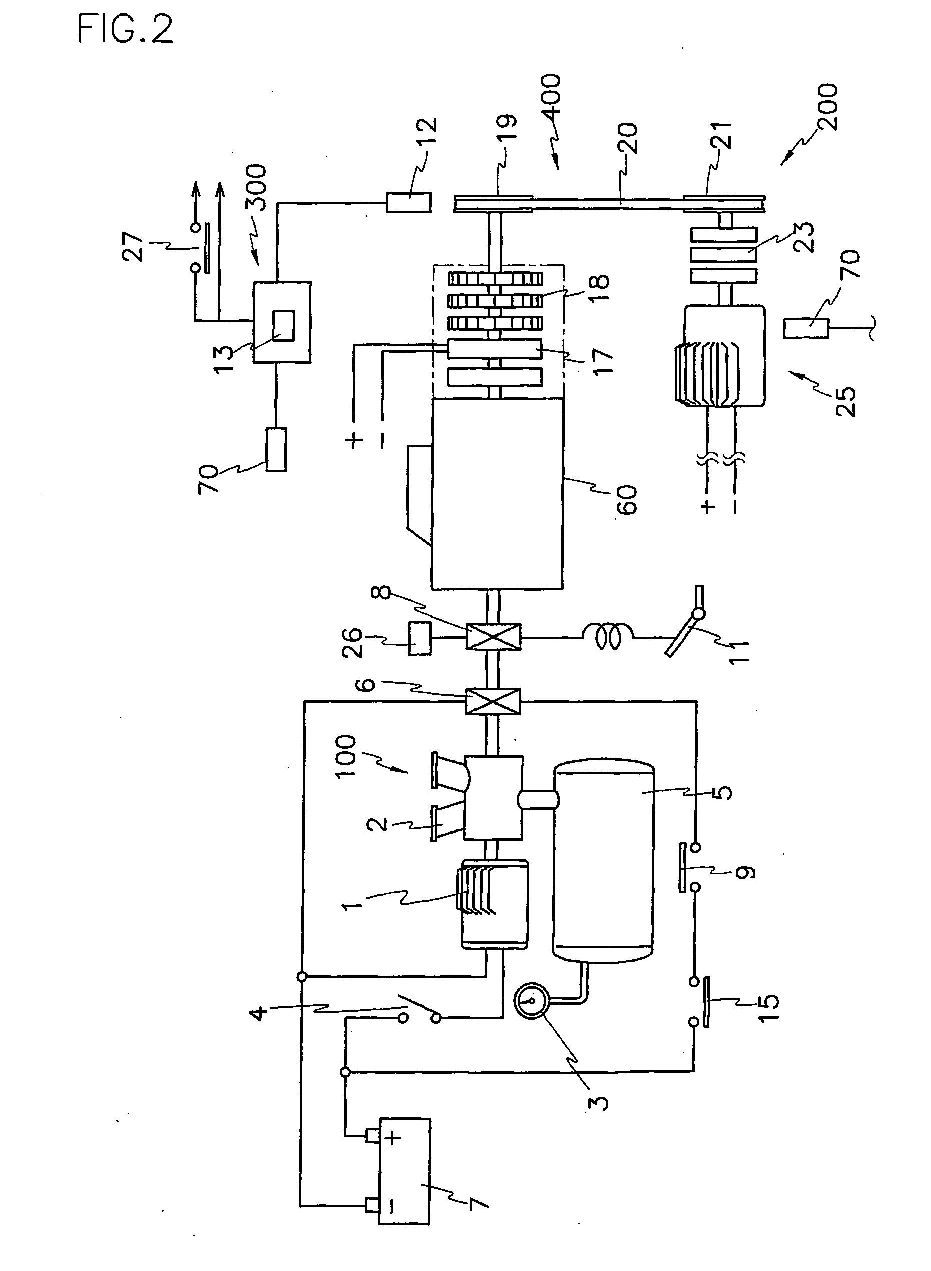
[0025] FIG. 1 shows a schematic perspective view of a PHEE according to a preferred embodiment of the present invention, FIG. 2 illustrates an air intake part of a PHEE depicted in FIG. 1, and FIG. 4 shows an electric circuit diagram of a PHEE according to a preferred embodiment of the present invention;

[0026] As shown in the drawings, the inventive PHEE (hybrid engine) comprises an air supplying part 100 for supplying compressed air, a pneumatic engine part 60 for generating power using the compressed air from the air supplying part 100, and an electric engine part 200 for generating power depending on the load of the pneumatic engine part 60.

[0027] In addition, the pneumatic engine part 60 and the electric engine part 200 are connected to a control part 200 so that they can be selectively controlled. That is, the control part 200 operates the pneumat...


PUM


Abstract

A pneumatic hybrid electric engine includes an electric source, an air supply part for compressing air and storing the compressed air, a pneumatic engine part for generating power using air supplied from the air supply part, an electric engine part for generating power using electric power applied from the electric source, a power transmission part for transmitting the power generated by the pneumatic engine part and the electric engine part, and a control part for selectively operating the pneumatic engine part and the electric engine part so that the pneumatic and electric engines parts can be switched on the basis of a predetermined torque range.

Description

[0001] (a) Field of the Invention[0002] The present invention relates to a pneumatic hybrid electric engine (PHEE) and, more particularly, to a PHEE that is a combination of a pneumatic engine and an electric motor engine, which can fully obtain initial start power by timely switching the power source from the pneumatic engine to the electric motor engine or vice versa according to the variation of the engine load.[0003] (b) Description of the Related Art[0004] Generally, an engine is a device for generating power that can be used for operating vehicles or ships. As the industry develops, a variety of engines have been proposed.[0005] In the initial stages of the industrial revolution, steam engines had usually been used. However, since the steam locomotives or steam ships using such a steam engine use a coal for fuel, the energy efficiency is very low while emitting noxious fumes.[0006] To solve the above problems, combustion engines using gasoline or diesel oil for fuel has been d...

Claims


Application Information

Patent Timeline
IPC IPC(8): B60K1/00B60K6/00B60K6/12B63H23/18
CPCB60K1/00B60L2200/26B60K6/12B63H23/18Y02T10/6208Y02T90/14B60L1/003B60L3/0061B60L3/0069B60L3/04B60L8/003B60L11/002B60L11/1803B60L2240/12B60L2240/36B60L2240/507B60L2240/547B60L2240/549B60L2250/16Y02T10/7005Y02T10/7083B60K6/00B60L50/51B60L50/90Y02T10/62Y02T10/70Y02T10/7072
Inventor CHO, CHOL-SEUNGKO, DAE-SIK
Owner PARKER INTANGIBLES LLC
Why Eureka
Try Eureka