Super-resolution overlay in multi-projector displays

a multi-projector display and super-resolution technology, applied in the field of light projector systems, can solve the problems of limiting the rendering of truly reliable realistic virtual scenes, dlps are proving highly scalable in resolution, and are more expensive than polysilicon panels

Inactive Publication Date: 2004-12-02
UNIV OF KENTUCKY RES FOUND
View PDF2 Cites 216 Cited by
  • Summary
  • Abstract
  • Description
  • Claims
  • Application Information

AI Technical Summary

Problems solved by technology

Today, DLPs are proving highly scalable in resolution, but are limited by being more expensive than polysilicon panels.
Although prior virtual display designs have attempted to overcome super-resolution (SR) issues encountered when employing multiple projector displays in various configurations, the resolution limitation of projectors has hindered the rendering of truly reliable realistic virtual scenes.
T

Method used


Image

  • Super-resolution overlay in multi-projector displays
  • Super-resolution overlay in multi-projector displays
  • Super-resolution overlay in multi-projector displays

Examples


Embodiment Construction

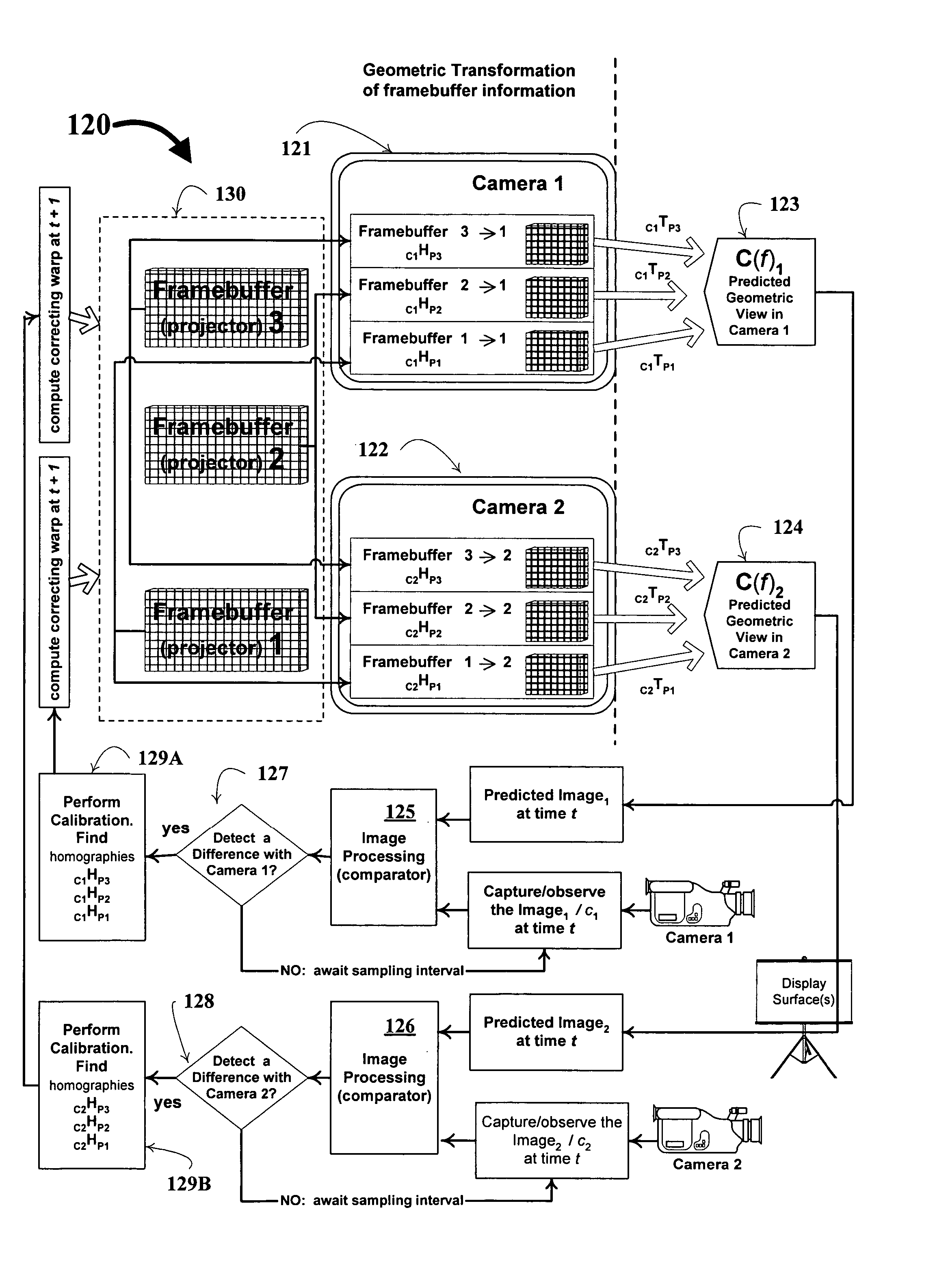
[0036] In connection with discussing the features in FIGS. 1-2, occasional reference will be made back-and-forth to other of the figures, all of which collectively detail core, as well as further unique and distinguishing features of technique of the invention at 10 and 50--and further providing a pictorial demonstration of the flexibility of design of this invention. As one can appreciate, the configuration of the simplified projector-camera pair system 100 in FIG. 6 is suitable for a wide variety of display shapes and environments.

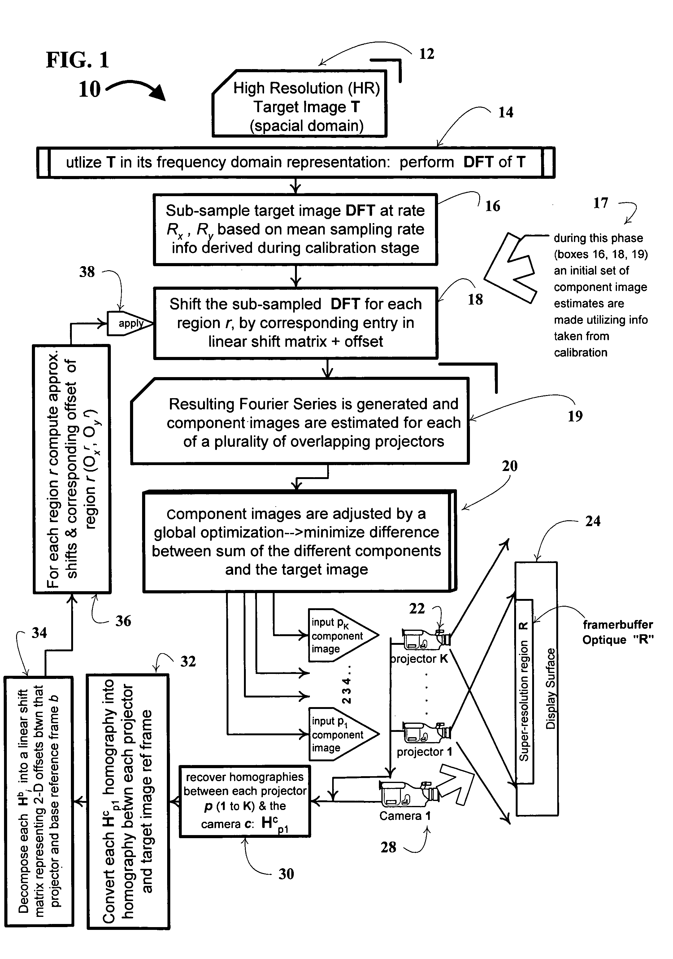
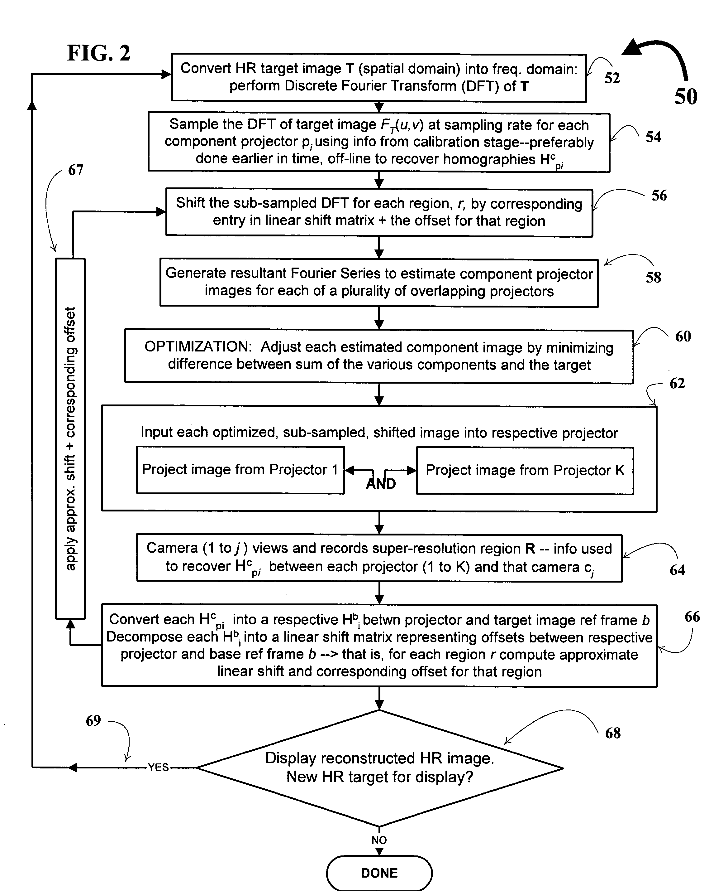
[0037] FIG. 1 depicts a multi-projector-camera system 10 in a flow-schematic fashion outlining core and additional features of the invention, having up-to k number of component projectors (22), each employed to display a component image that contributes to the superimposed image--identified as Framebuffer Optique, R--onto a display surface 24. Framebuffer Optique, R is under observation by camera 28. FIG. 2 is a flow diagram depicting details of a method...


PUM


Abstract

A technique, associated system and computer executable program code, for projecting a superimposed image onto a target display surface under observation of one or more cameras. A projective relationship between each projector being used and the target display surface is determined using a suitable calibration technique. A component image for each projector is then estimated using the information from the calibration, and represented in the frequency domain. Each component image is estimated by: Using the projective relationship, determine a set of sub-sampled, regionally shifted images, represented in the frequency domain; each component image is then composed of a respective set of the sub-sampled, regionally shifted images. In an optimization step, the difference between a sum of the component images and a frequency domain representation of a target image is minimized to produce a second, or subsequent, component image for each projector. Here, a second set of frequency domain coefficients for use in producing a frequency domain representation of the second component image for each projector is identified. Taking the inverse Fourier transform of the frequency domain representation of the second component image, converts the information into a spatial signal that is placed into the framebuffer of each component projector and projected therefrom to produce the superimposed image.

Description

[0001] This application claims the benefit of pending U.S. provisional patent application No. 60 / 464,218 filed 19 Apr. 2003 for the applicants on behalf of the assignee hereof.Field of the Invention[0003] In general, the present invention relates to light projector systems used for displaying information on a target surface--in the form of a superimposed image of images being projected from multiple projectors--that is under observation of at least one camera. Traditional super-resolution (SR) reconstruction is the process of combining low resolution (LR) images projected from a multiple of front-projection devices in an attempt to recover a higher resolution image. More-particularly, the invention is directed to a technique and system for projecting a superimposed image onto a target display surface under observation of one or more cameras. First, a projective relationship between each projector being used and the target display surface is determined using a suitable calibration te...

Claims


Application Information

Patent Timeline
IPC IPC(8): G03B21/26H04N5/74
CPCH04N9/3147
Inventor JAYNES, CHRISTOPHER O.RAMAKRISHNAN, DIVYA T.
Owner UNIV OF KENTUCKY RES FOUND
Why Eureka
Try Eureka