Method and apparatus for producing thin walled tubular product with thick walled flange

a technology of thick walled tubular products and flanges, which is applied in forging/pressing/hammering equipment, manufacturing tools, forging/hammering/hammering machines, etc., can solve the problems of substantial increase in production costs, increased device cost and operating costs, and increased transfer process costs

Inactive Publication Date: 2004-12-09
MATSUOKA MINAKO +2
View PDF10 Cites 55 Cited by
  • Summary
  • Abstract
  • Description
  • Claims
  • Application Information

AI Technical Summary

Problems solved by technology

Therefore, in order to obtain a flange portion of an increased wall thickness exceeding several percent of the wall thickness of a blank, a combined process is essential, where a separate flange member of a desired wall thickness is prepared and a welding of separate flange member is done, resulting in a substantial increase in a production cost.
As a result, only two stage metal working processes are enough for obtaining a tubular product with an increased thickness exceeding a several percent over the thickness of the blank plate.
However, an excessively increased thickness may likely cause a buckling to be generated during the execution of the leveling or flattening and, therefore, the upper limit of the incli

Method used


Image

  • Method and apparatus for producing thin walled tubular product with thick walled flange
  • Method and apparatus for producing thin walled tubular product with thick walled flange
  • Method and apparatus for producing thin walled tubular product with thick walled flange

Examples


Embodiment Construction

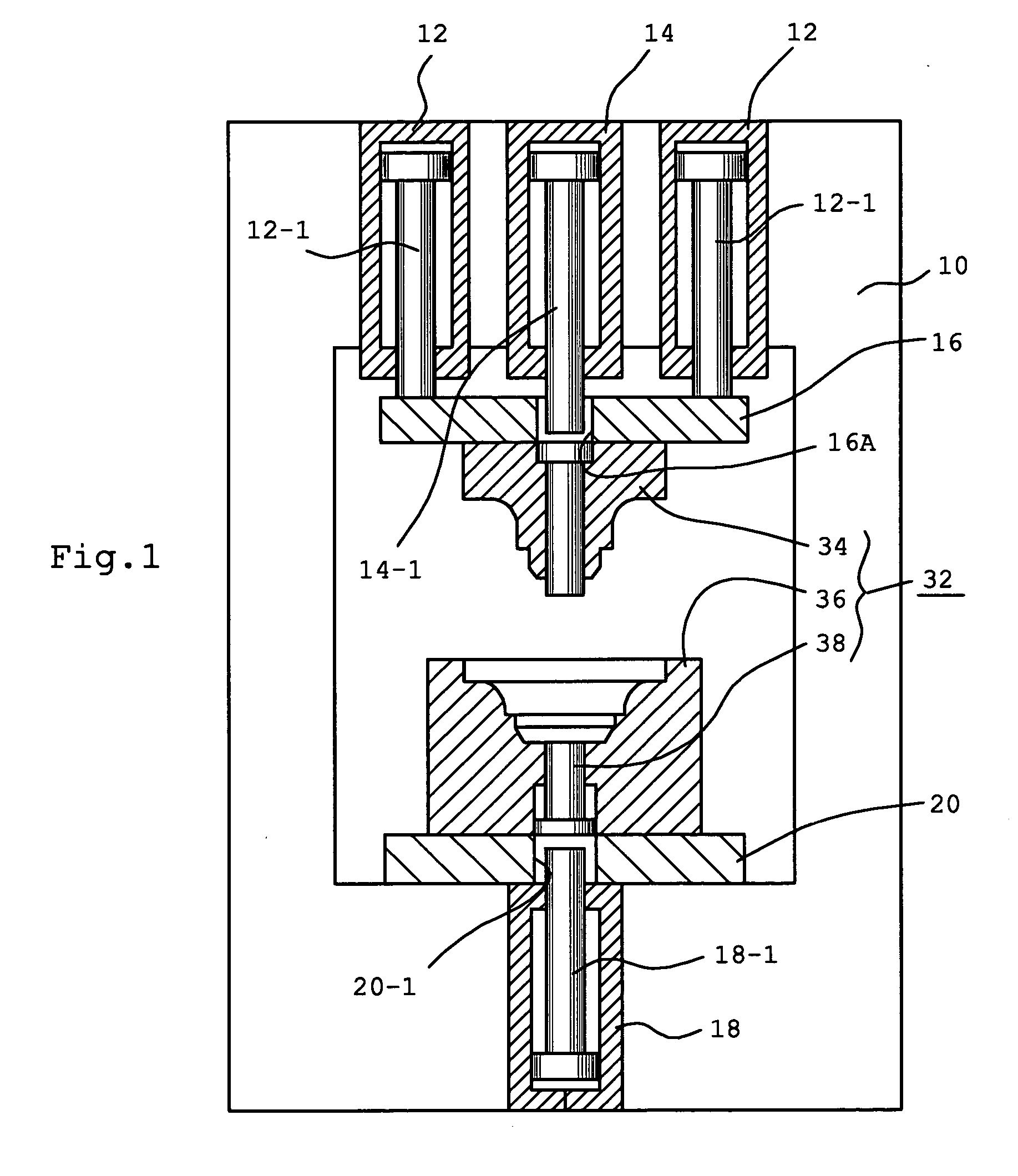
[0048] Referring to FIG. 1, an embodiment of the present invention embodied as a hydraulic pressing apparatus of a three-axis type is schematically illustrated. The apparatus is shown in a condition that a second die set 32 as described later in more detail is mounted. The apparatus is provided with a frame 10, on the upper part of which a pair of laterally spaced first hydraulic cylinders 12 as a first axis unit as well as a central second hydraulic cylinder 14 as a second axis unit are provided. The first hydraulic cylinder 12 has a piston rod 12-1 having a bottom end, which is in connection with a slide table 16. The second hydraulic cylinder 14 has a piston rod 14-1, which is freely passed through an opening 16A formed at the center of the slide table 16. Arranged at the lower part of the main frame 10 is a hydraulic cylinder 18, which constructs a third axis unit. The hydraulic cylinder 18 has a piston rod 18-1 having an upper end passed freely through a central opening 20-1 in...


PUM

PropertyMeasurementUnit
Angleaaaaaaaaaa
Thicknessaaaaaaaaaa
Angleaaaaaaaaaa

Abstract

Method and apparatus for producing a thin walled tubular product with thickened flange. A first stage metalworking (drawing) of a circular plate material A is done by using a first die set 22 having a conical die 24 and a drawing punch 26 is done in a manner that the end of the blank plate is remained on the conical surface 24-1 of the die, so that a semi-finished tubular product A1 with a inclined flange A1-1 is obtained. Then, a second stage metalworking (drawing) of the semi-finished tubular product A1 is done by a second die set 32 having a shaping punch 34 and a restraint die 36. The semi-finished tubular product A1 is held by the restraint die 36 and the shaping punch 34 is introduced into the semi-finished tubular product A1 for effecting a wall thickness reduction under ironing principle while forming a stepped portion. Simultaneous with the execution of the second stage drawing, a flattening of the flange is done while restriction diameter expansion by a wall 40, thereby obtaining a thickened flattened flange A2-3.

Description

[0001] 1. Field of the Invention[0002] The present invention relates to a method for forming, from a metal plate, a tubular product with a thickened flange portion, combined dies for a press apparatus, and a three axis press apparatus.[0003] 2. Description of Related Art[0004] Japanese Un-Examined Patent Publication 2001-1060 discloses a method for forming a tubular product with a thickened flange portion from a metal plate (blank), wherein the metal plate is rested on a die of a circular conical shape and is subjected, as a first stage metal working, to a drawing by a punch. The drawing is ceased under a condition that the flange portion of the blank is still stayed on a circular conical surface of the circular conical shaped die, so that an semi-finished product of a cup shape having an inclined flange portion is obtained. The cup shaped semi-finished product is, then, subjected to a second stage metal working, wherein the inclined flange portion of the cup shaped semi-finished pr...

Claims


Application Information

Patent Timeline
IPC IPC(8): B21D22/26B21D22/02B21D22/20B21D28/24B21D51/18B21K21/10B21K23/04
CPCB21D22/02B21K21/10B21K23/04B21D35/001B21D51/10
Inventor SHIOKAWA, SEIJI
Owner MATSUOKA MINAKO
Why Eureka
Try Eureka