Picture encoding device, image decoding device and their methods

a technology of image encoding and decoding device, which is applied in the direction of color television with bandwidth reduction, television system, instruments, etc., can solve the problems of low prediction efficiency, inability to handle the vast information directly in digital form via the information media mentioned, and inability to transmit the moving picture captured on the tv screen or shot by a tv camera

Active Publication Date: 2004-12-09
GK BRIDGE 1
View PDF16 Cites 108 Cited by
  • Summary
  • Abstract
  • Description
  • Claims
  • Application Information

AI Technical Summary

Benefits of technology

0039] The present invention has been conceived in view of the aforementioned circumstances and aims to provide a picture coding/deco

Problems solved by technology

Therefore, it is not realistic to handle the vast information directly in digital form via the information media mentioned above.
For example, a videophone has already been put into practical use via Integrated Services Digital Network (ISDN) with a transmission rate of 64 Kbps.about.1.5 Mbps, however, it is not practical to transmit the moving picture captured on the TV screen or shot by

Method used


Image

  • Picture encoding device, image decoding device and their methods
  • Picture encoding device, image decoding device and their methods
  • Picture encoding device, image decoding device and their methods

Examples


second embodiment

[0123] The present embodiment describes an example of a case in which a data structure of a picture area is different from the one illustrated in the first embodiment.

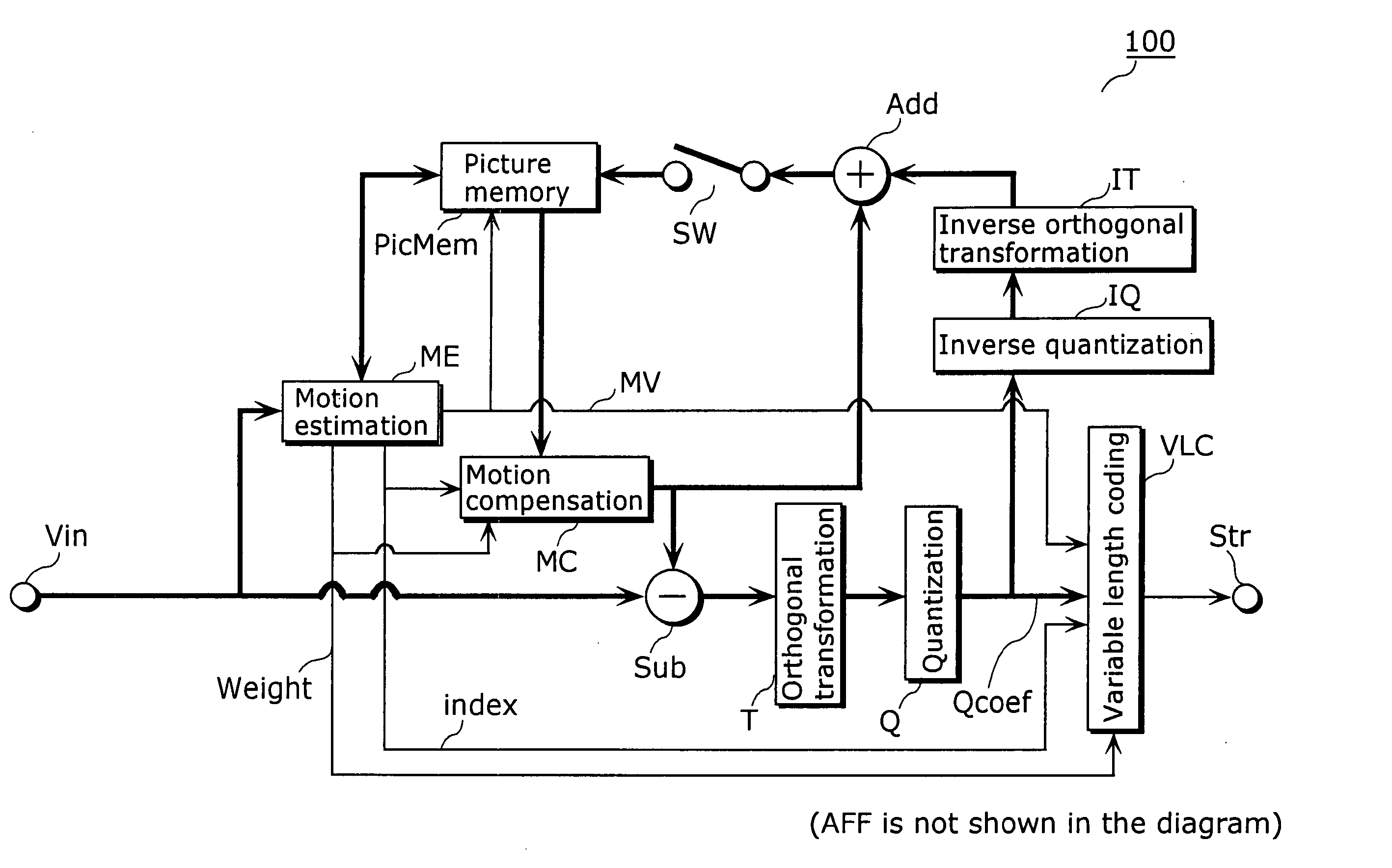
[0124] FIGS. 17A, 17B and 17C are diagrams showing examples of a data structure of a picture area according to the present embodiment. These diagrams also show a detailed data structure of a "header" included in a common information area in a picture area. The present embodiment illustrates an example of a structure of the "header" from which a field weighting factor can be abbreviated when the "picture frame coding information" indicates "1" and the picture is coded on a frame-by-frame basis.

[0125] As shown in FIGS. 17A and 17B, the "header" includes "Field factor presence / absence information" as well as the "AFF". The "Field factor presence / absence information" is a flag indicating whether or not the "header" has a field weighting factor. For example, the flag is set to "1" when the "header" has the field weighting f...

third embodiment

[0138] The present embodiment describes a case in which the data structure of the picture area is different from the one illustrated in the first embodiment.

[0139] FIGS. 20A, 20B and 20C are diagrams showing examples of the data structure of the picture area according to the present embodiment. It shows a detailed data structure of a "header" when the "picture frame coding information" included in a common information area in a picture area indicates "1" and the picture is coded on a frame-by-frame basis. The present embodiment illustrates an example of the structure of the "header" from which the frame weighting factor can be abbreviated.

[0140] As shown in FIGS. 20A and 20B, the "header" includes the "Frame factor presence / absence information" as well as the "AFF". The "Frame factor presence / absence information" is a flag indicating whether or not the "header" includes the frame weighting factor. For example, the flag is set to "1" when the frame weighting factor is found and is se...

fourth embodiment

[0151] Furthermore, the processing shown in each of the above embodiments can be carried out easily in an independent computer system by recording the program for realizing the picture coding / decoding method described in each of the above embodiments onto a storage medium such as a flexible disk or the like.

[0152] FIG. 23 is an illustration for carrying out the picture coding / decoding method described in each of the above embodiments in the computer system using the program recorded onto the storage medium such as a flexible disk or the like.

[0153] FIG. 23B shows a full appearance of a flexible disk, its structure at cross section and the flexible disk itself whereas FIG. 23A shows an example of a physical format of the flexible disk as a main body of a storage medium. A flexible disk FD is contained in a case F with a plurality of tracks Tr formed concentrically from the periphery to the inside on the surface of the disk, and each track is divided into 16 sectors Se in the angular ...


PUM


Abstract

A weighting factor mode determination unit (13) determines whether to code an interlaced picture in a field mode or a frame mode, based on a value of a flag "AFF" indicating whether or not to switch between the field mode and the frame mode on a block-by-block basis and notifies switches (14 and 15) and a multiplexing unit (106) of the determined mode. The switches (14 and 15) select either the field mode or the frame mode according to the notified mode. A field weighting factor coding unit (11) or a frame weighting factor coding unit (12) performs respectively the coding of respective weighting factors when the respective modes are selected.

Description

[0001] The present invention relates to a coding apparatus and a decoding apparatus for coding and decoding moving pictures, especially to a picture coding apparatus and a picture decoding apparatus for performing motion estimation using weighting factors and the methods thereof.[0002] Recently, with an arrival of the age of multimedia which handles integrally audio, picture, other contents or the like, it is now possible to obtain or transmit the information conveyed by existing information media, i.e., newspapers, journals, TVs, radios and telephones and other means using a single terminal. Generally speaking, multimedia refers to something that is represented in association not only with characters but also with graphics, audio and especially pictures and the like together. However, in order to include the aforementioned existing information media in the scope of multimedia, it appears as a prerequisite to represent such information in digital form.[0003] However, when estimating...

Claims


Application Information

Patent Timeline
IPC IPC(8): G06T9/00H04N19/50H04N19/13H04N19/159H04N19/46H04N19/503H04N19/70H04N19/85H04N19/91
CPCH04N19/105H04N19/176H04N19/16H04N19/196H04N19/112H04N19/70H04N19/51H04N19/172
Inventor KADONO, SHINYAKONDO, SATOSHIABE, KIYOFUMI
Owner GK BRIDGE 1
Why Eureka
Try Eureka