Multi-user detection

a detection solution and multi-user technology, applied in the field of multi-user detection, can solve the problems of expensive evaluation of r and inability to try all

Inactive Publication Date: 2004-12-09
LENSLET
View PDF6 Cites 31 Cited by
  • Summary
  • Abstract
  • Description
  • Claims
  • Application Information

AI Technical Summary

Benefits of technology

[0026] An aspect of some embodiments of the invention relates to a method of matrix tracking, in which a byproduct of the use of the matrix is used for tracking. In an exemplary embodiment of the invention, an error value is used as part of a main process to determine a likely set of data from samples, for example for a match filter. This error value is used to update the matrix. Optionally, the error is added using a weight, for example to prevent noise from causing divergence in the tracking.
[0038] In an exemplary embodiment of the invention, match-filtering comprises match-filtering using vector-matrix multiplication. Optionally, the method comprises arranging said data to fit a specific hardware adapted for vector matrix multiplication. Optionally, arranging comprises arranging said data in a manner which minimizes matrix replacements.

Problems solved by technology

Since, even in the binary case there are 2.sup.P possible solutions X, it is not practical to try them all when p is large.
Another disadvantage of this procedure is that R is expensive to evaluate because it involves multiplying two non-diagonal matrixes, A.sup.T and A, and this matrix multiplication must be done repeatedly if we wish to track A as it changes with time.

Method used


Image

  • Multi-user detection
  • Multi-user detection
  • Multi-user detection

Examples


Embodiment Construction

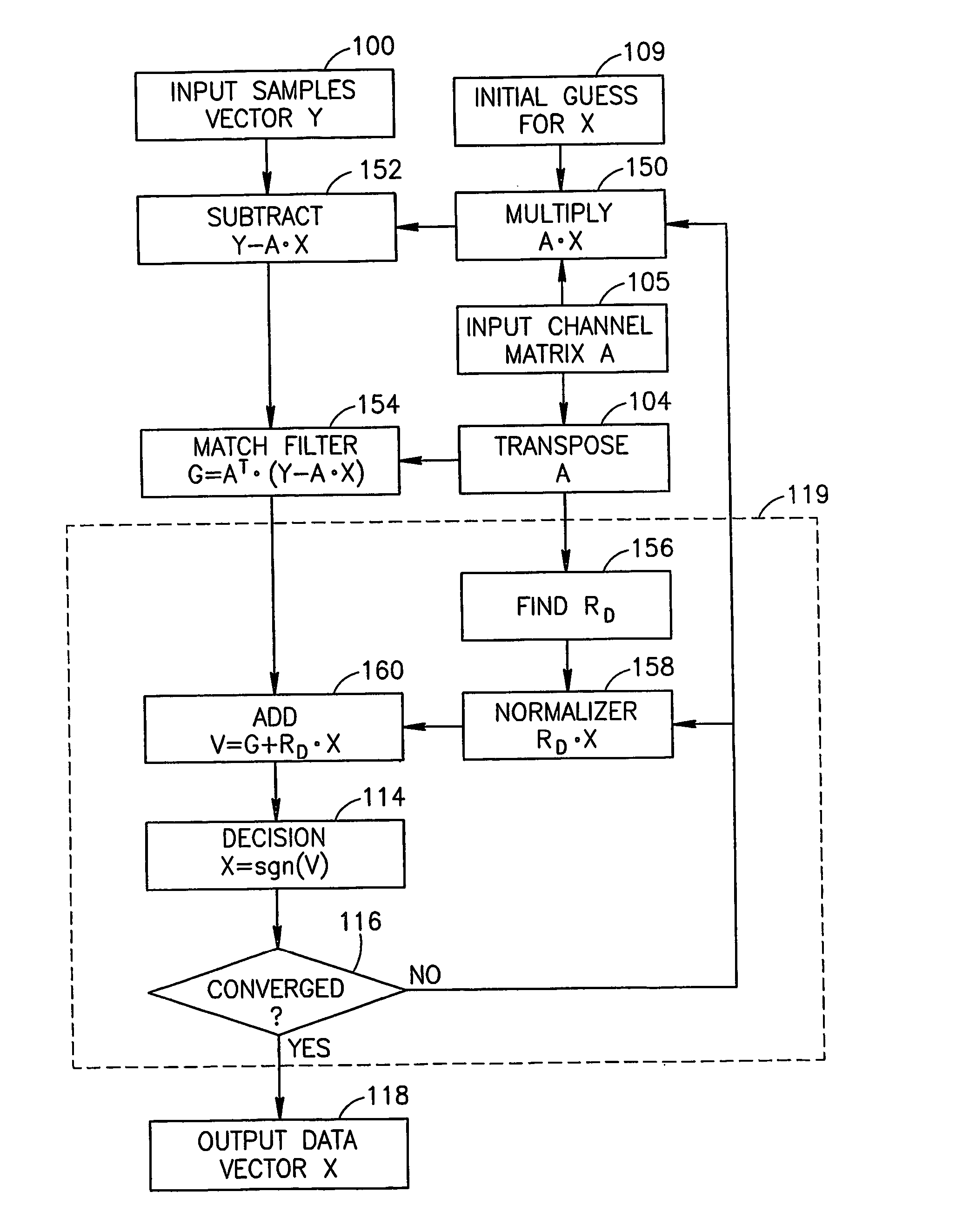
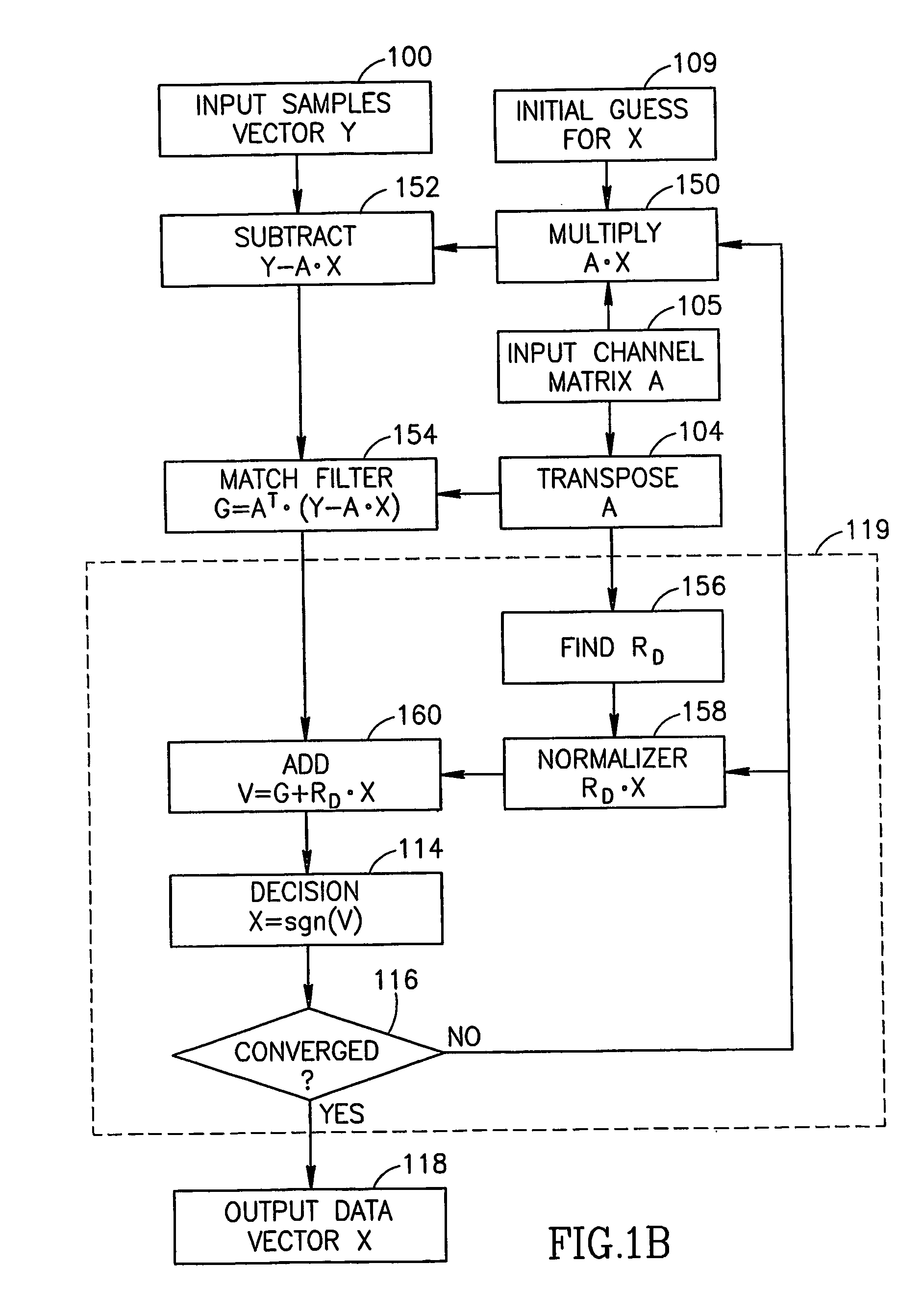
[0090] FIG. 1B is a flow diagram showing the procedure used according to an exemplary embodiment of the invention, to search for a the Multi User Maximum Likelihood solution for a transmitted channel vector X, with known received sample vector Y and channel matrix A, in the presence of noise, and with interference between the different channels, i.e. with off-diagonal terms in A.

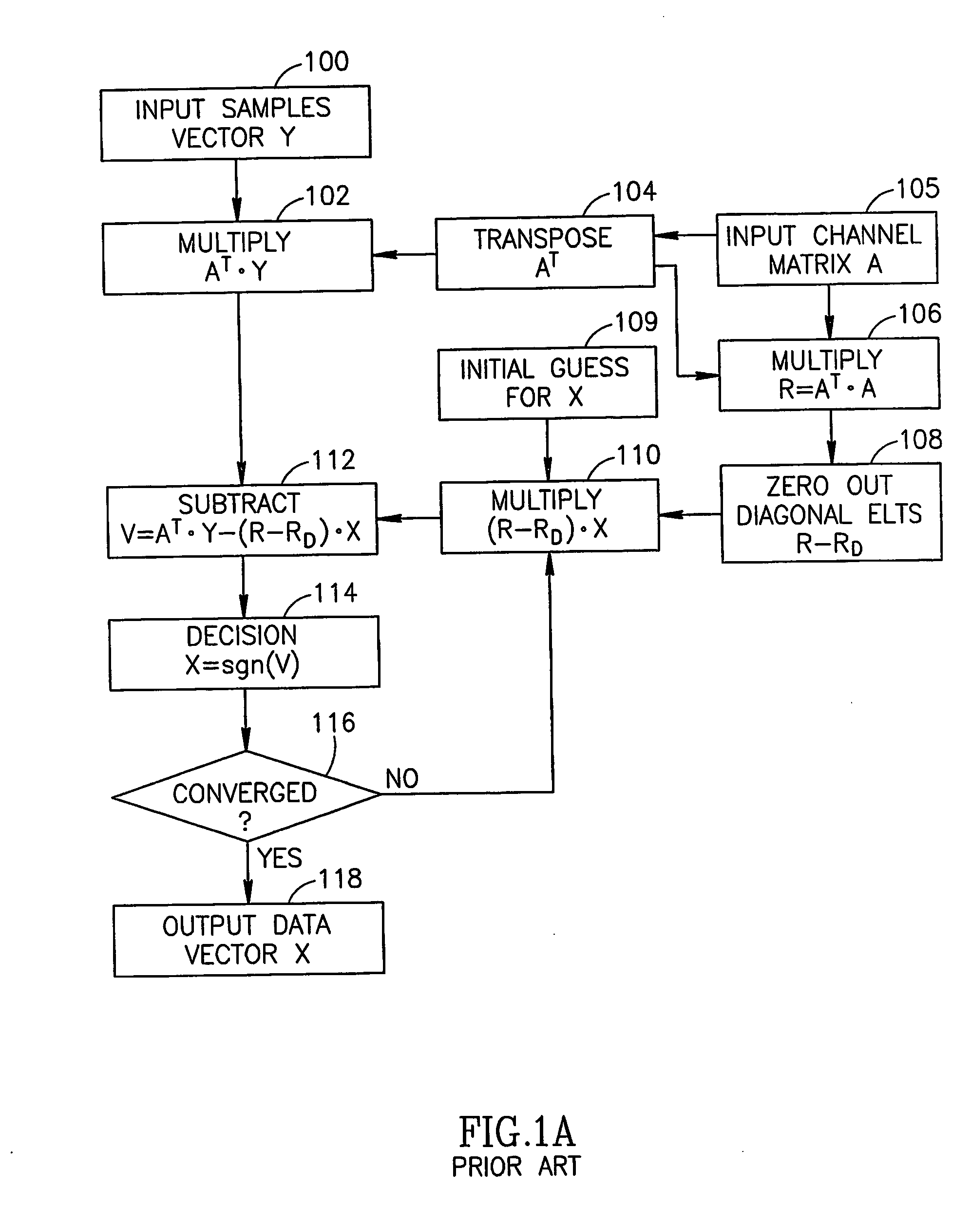
[0091] In FIG. 1B, as in FIG. 1A, the sample vector Y is read in as input at 100, the transpose A.sup.T of the channel vector A is found at 104 after A is read as input at 105, and an initial estimate for the channel vector X is read as input at 109. In an exemplary embodiment of the invention, the procedure in FIG. 1B differs from the prior art procedure shown in FIG. 1A, for example, in the way that the vector V is calculated. In FIG. 1B, the current estimate for X is multiplied by A at 150, and subtracted from Y at 152. The difference Y-A.multidot.X is multiplied by A.sup.T at 154 to find the gradient vec...


PUM


Abstract

A method of finding a maximum likelihood solution for, comprising: providing a sample vector; iteratively match-filtering said sample vector with a coefficient matrix to find a gradient; using the gradient to search for a maximum likelihood solution; and deciding if a found solution of vector data is good enough.

Description

[0001] This invention is in the field of signal processing, in particular methods of reducing interference between multiple users of a communication channel.[0002] Consider a communication system comprising p channels carrying digital signals X={X.sub.1, X.sub.2, . . . X.sub.p}, with each X.sub.i equal to +1 or -1. There are also q received samples Y={Y.sub.1, Y.sub.2, . . . Y.sub.q}, where q is typically greater than p. Among other possibilities, the different channels could represent different frequency bands, or different time slots in a shared frequency band, or the channels could be defined by Code Division Multiple Accesses (CDMA), in which each of p channels is associated with a different one of p different orthogonal binary codes, each p bits long. In general there is receiver noise in each channel described by a vector N={N.sub.1, N.sub.2, . . . N.sub.q}, and there is attenuation or amplification in each channel, and cross-talk between channels, described by the elements A....

Claims


Application Information

Patent Timeline
Patent Type & Authority Applications(United States)
IPC IPC(8): G06EG06E1/04H04B1/707H04B7/005H04B7/01H04B7/015H04B15/00H04L27/06H04Q
CPCH04B1/7093H04B1/7105H04B1/71057
Inventor MOLEV SHTEIMAN, ARKADY
Owner LENSLET
Why Eureka
Try Eureka