

Method and apparatus for producing droplet spray
- Summary
- Abstract
- Description
- Claims
- Application Information
AI Technical Summary
Benefits of technology
Problems solved by technology
Method used
Image

Examples
first embodiment
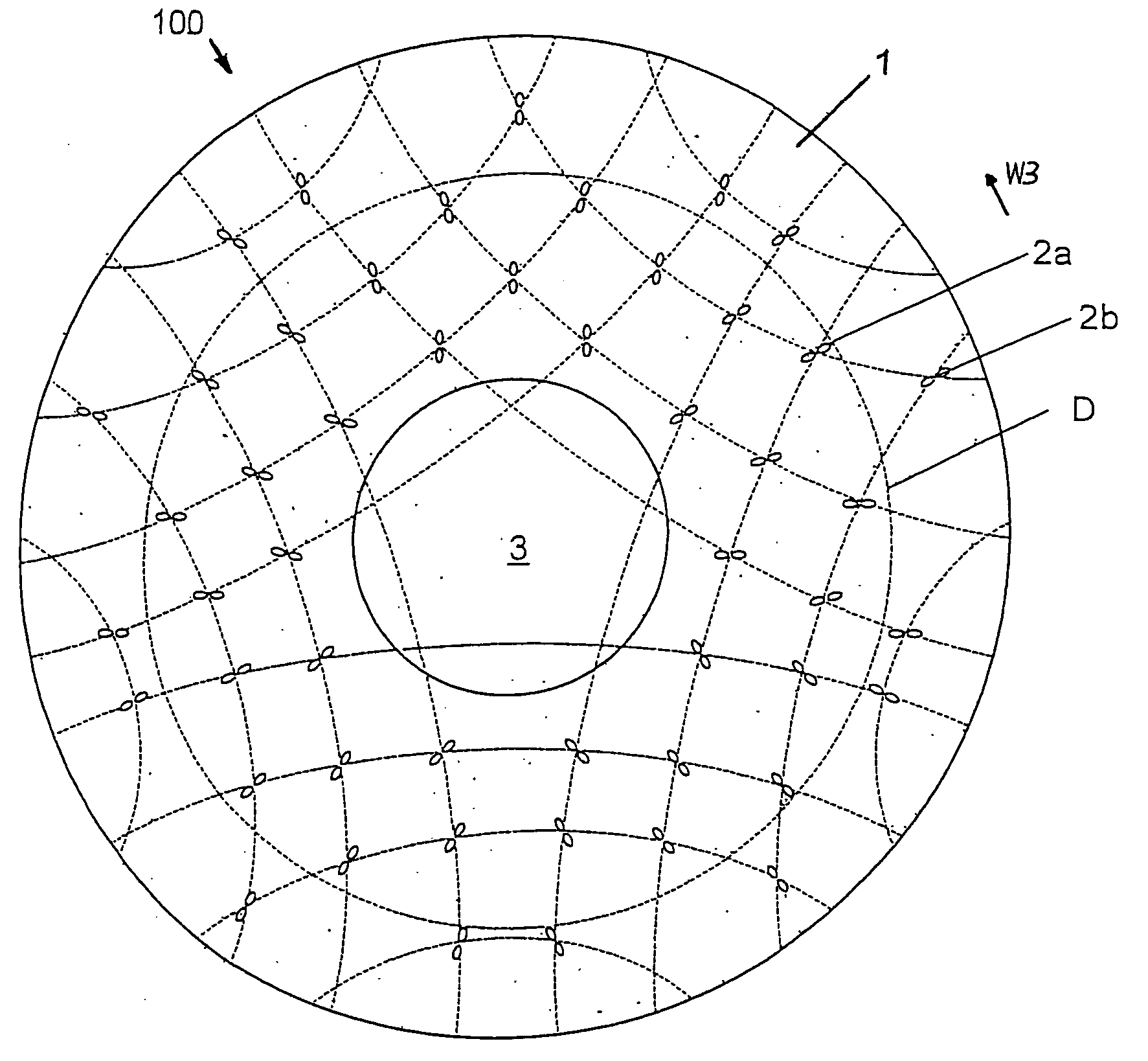
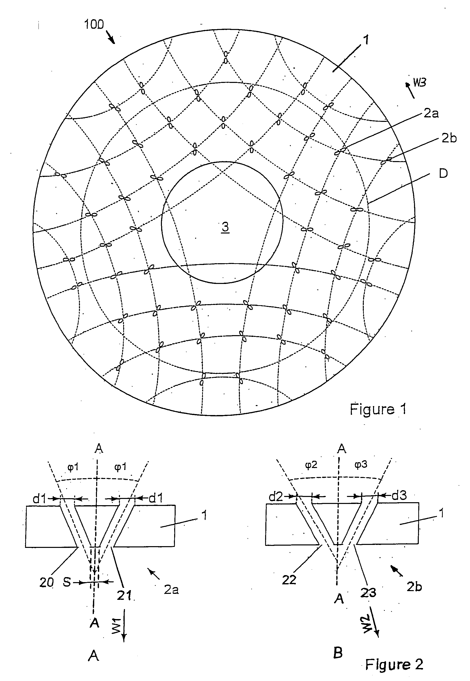
[0052] Referring to FIG. 1 of the accompanying drawings, a spray head insert according to the present invention is shown and generally referenced by arrow 100. The spray head insert 100 may have particular application to a shower head and have advantages that particularly suit it to use as a shower head, but the application of the present invention is not limited solely to shower heads. For example, the spray head of the present invention may have application to industrial processes, including the application of paint or adhesive and / or to agricultural applications, including the application of herbicide or insecticide. It is anticipated that the present invention may have application where a soft spray, rather than a spray made up of a number of jets is required. The spray head 100 may be used as an emergency shower for treatment of burns victims immediately after the accident occurred.
[0053]FIG. 3 shows a pattern of water resulting from the convergence of two fluid jets exiting fr...
second embodiment
[0068] In the invention, the nozzles may be a separate component engageable with the rest of the spray head. Also, the nozzles may be formed by discrete nozzles engaged with the base 1. An example of this embodiment is shown in FIGS. 4A and 4B. FIGS. 4A and 4B show a nozzle group 2c including two nozzles 26, 27. The nozzle group 2c is an integral moulded component, suitably of moulded rubber and is inverted and inserted into an aperture 11 in a base 10 (see FIG. 4B), the base 10 forming part of a spray head. A central support 28 sets the distance S1 between the nozzles 26, 27. The nozzles 26, 27 and support 28 extend from a foot 29, which abuts the inside surface of the base 10, assisting to prevent the nozzles 26, 27 being pushed through the aperture 11. Multiple groups of nozzles 2c, may extend from the same foot 29 and all the nozzles for a spray head may be provided on a single foot, forming an insert for a spray head base.
[0069] An advantage of the embodiment shown in FIG. 4B i...
PUM
 Abstract
Description
Claims
Application Information