Active type vibration isolating support system

a technology of active type and support system, which is applied in the direction of machine support, shock absorber, mechanical apparatus, etc., can solve the problems of inability to achieve the initial air gap described and increase the cost, and achieve the effect of obtaining the desired vibration isolating characteristi

Active Publication Date: 2005-01-06
HONDA MOTOR CO LTD +1
View PDF5 Cites 11 Cited by
  • Summary
  • Abstract
  • Description
  • Claims
  • Application Information

AI Technical Summary

Benefits of technology

[0007] The present invention has been achieved in view of the above-described circumstances, and has an object to provide a low-priced active type vibration isolating support system capable of e

Problems solved by technology

In the active type vibration isolating support system, characteristics of the movable member concerning thrust and displacement are dependent on an initial air gap between attracted surfaces of those fixed and movable cores of the actuator, but the above-described initial air gap may not

Method used


Image

  • Active type vibration isolating support system
  • Active type vibration isolating support system
  • Active type vibration isolating support system

Examples


first embodiment

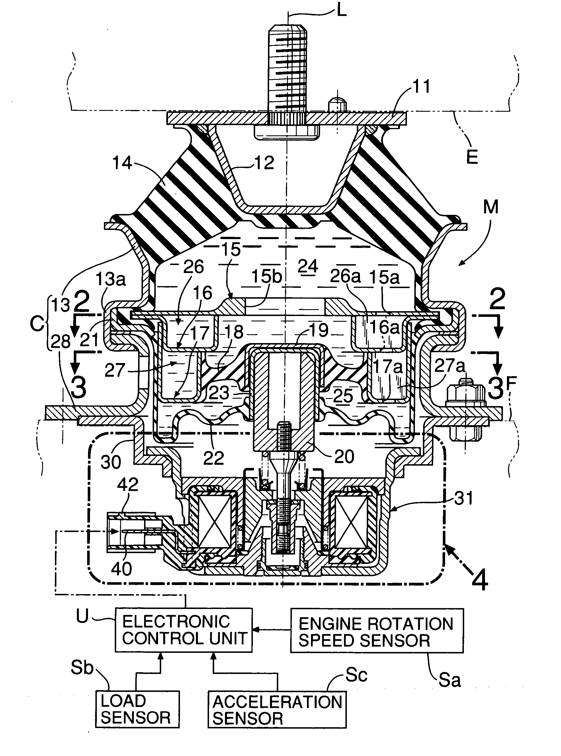
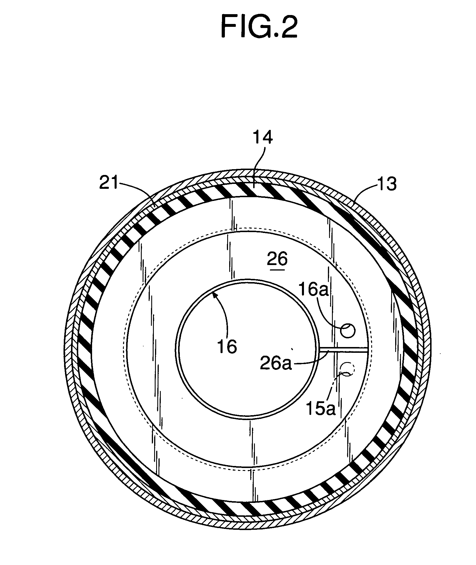
[0025] First, the present invention shown in FIG. 1 to FIG. 4 will be described. In FIG. 1, an active type vibration isolating support system M is, in order to elastically support the engine E on the body frame F in an automobile, interposed therebetween.

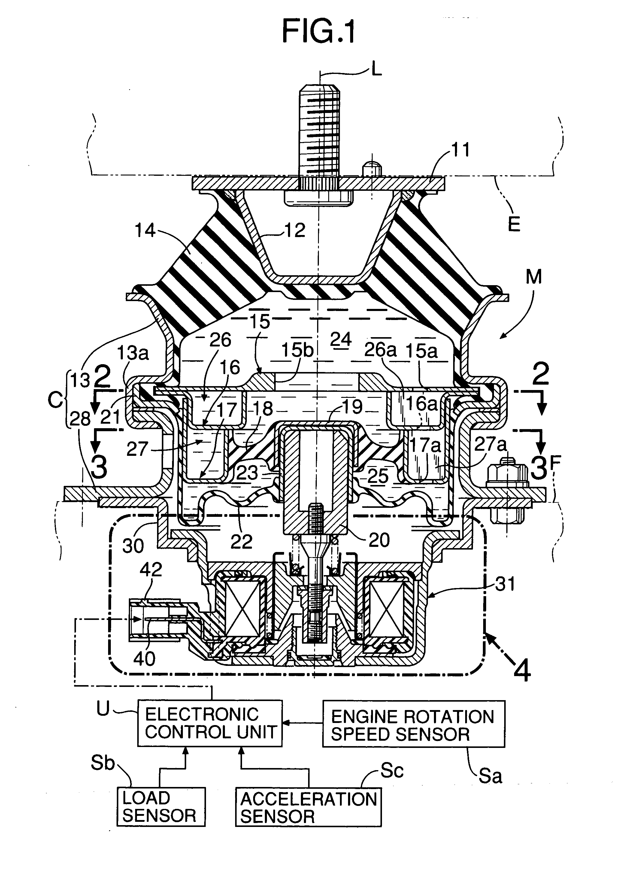
[0026] The active type vibration isolating support system M has actually axisymmetric structure with respect to an axis L, and has a plate-shaped installation bracket 11 to be connected to the engine E; an inner tube 12 welded to this installation bracket 11; an outer tube 13 which is coaxially arranged around an outer periphery of this inner tube 12; and a first elastic body 14 made of thick rubber or the like to be vulcanized and bonded onto conical surfaces of these inner tube 12 and outer tube 13 which oppose to each other. Below this first elastic body 14, there are arranged a first orifice formation member 15, a second orifice formation member 16 and a third orifice formation member 17, which are arranged vertically and made i...

second embodiment

[0071] Next, the description will be made of the present invention shown in FIG. 9.

[0072] This second embodiment is different from the first embodiment in closed structure of an adjustment operating hole 60 of the fixed core 33. More specifically, the adjustment operating hole 60 is constructed by lining fitted holes 60c having a large diameter to the lower end of the simple through-hole 60a having no thread via an annular shoulder portion 60b, and the inner peripheral surface of the fitted hole 60c is provided with an annular restraining groove 58. On the other hand, a peg body 61 corresponds to one obtained by cutting off the threaded tube 61a from the peg body 61 of the first embodiment. In the fitted hole 60c, a collar portion 61b of the peg body 61 is fitted via a sealing member 64, and between this collar portion 61b and the shoulder portion 60b at the upper end of the fitted hole 60c, there is interposed an elastic member 72 such as a wave washer. Thus, in a state in which th...


PUM


Abstract

An active type vibration isolating support system includes: an elastic body for elastically supporting a vibratory body; a liquid chamber to be defined by the elastic body; a movable member for changing capacity of the liquid chamber; and an actuator for driving the movable member. The actuator has: a fixed core; a movable core coupled to the movable member for being arranged opposite to the fixed core via an air gap; and a coil for generating an electromagnetic attracting force between the fixed and movable cores. The movable member and the movable core are coupled together through coupling units capable of adjusting the air gap. Thus, without preparing several types of coupling members, it is possible to obtain a desired vibration isolating characteristic by freely adjusting the air gap between the fixed core and the movable core.

Description

BACKGROUND OF THE INVENTION [0001] 1. Field of the Invention [0002] The present invention relates to improvement of an active type vibration isolating support system comprising: an elastic body for elastically supporting a vibratory body on a supporting system; a liquid chamber which is defined by this elastic body and in which liquid is sealed; a movable member for changing capacity of this liquid chamber; and an actuator for driving this movable member, the system being electromagnetically constructed with the actuator equipped with: a fixed core which is supported by the supporting system; a movable core which is coupled to the movable member and is arranged opposite to this fixed core; and a coil for generating an electromagnetic attracting force between these fixed and movable cores. [0003] 2. Description of the Related Art [0004] Such an active type vibration isolating support system is already known as disclosed in, for example, Japanese Patent Application Laid-Open No. 2001-...

Claims


Application Information

Patent Timeline
IPC IPC(8): F16F13/26F16M5/00
CPCF16F13/264
Inventor KON, HIROZUMIKANEKO, TOMOHIKONEMOTO, HIROTOMIUE, HIROAKIMIKASA, TETSUOIINUMA, KEN
Owner HONDA MOTOR CO LTD
Why Eureka
Try Eureka