Sheet material clamp

a technology of sheet material and clamping rod, which is applied in the direction of washstands, scaffold accessories, lighting support devices, etc., can solve the problems of enhancing the risk of destroying the edge of the countertop, c-clamps are difficult to use in this application, and it is difficult to get an even application of pressure along the edge with a series of individual clamps, so as to achieve efficient and quick application of clamping pressure

Inactive Publication Date: 2005-01-06
CROSS CHRISTOPHER TODD
View PDF8 Cites 15 Cited by
  • Summary
  • Abstract
  • Description
  • Claims
  • Application Information

AI Technical Summary

Benefits of technology

[0010] One aspect of the present invention is a sheet material clamp having a rigid clamp base of a pre-selected length. The length of the clamp base should substantially equal or exceed the length of the countertop edge being clamped. The rigid clamp base has a clamping surface running along its length and at least two clamping apparatus rigidly bonded to the clamping base. The clamping apparatus function by applying clamping pressure through a pressure foot toward the clamping surface. The apparatus for applying clamping pressure are preferably spaced along the length of the clamp base so that clamping pressure will be applied evenly along the edge of the countertop being fabricated.
[0013] The present invention provides a sheet material clamp which can be used to efficiently and quickly apply clamping pressure to two lengthwise portions of sheet material which are being bonded together. In addition, the sheet material clamp is optimized to provide pressure which is evenly distributed along the length of the materials being bonded. Furthermore, the present invention provides a clamp structure that can quickly clamp edges having inner or outer corners or radii.

Problems solved by technology

However, the use of C-clamps in this application can be difficult since numerous separate clamps must be applied along the countertop edge and it can be difficult to get an even application of pressure along the edge with a series of individual clamps.
These complicated edge configurations can further enhance the risk of ruining countertop edges by not applying suitable pressure.

Method used


Image

  • Sheet material clamp
  • Sheet material clamp
  • Sheet material clamp

Examples


Embodiment Construction

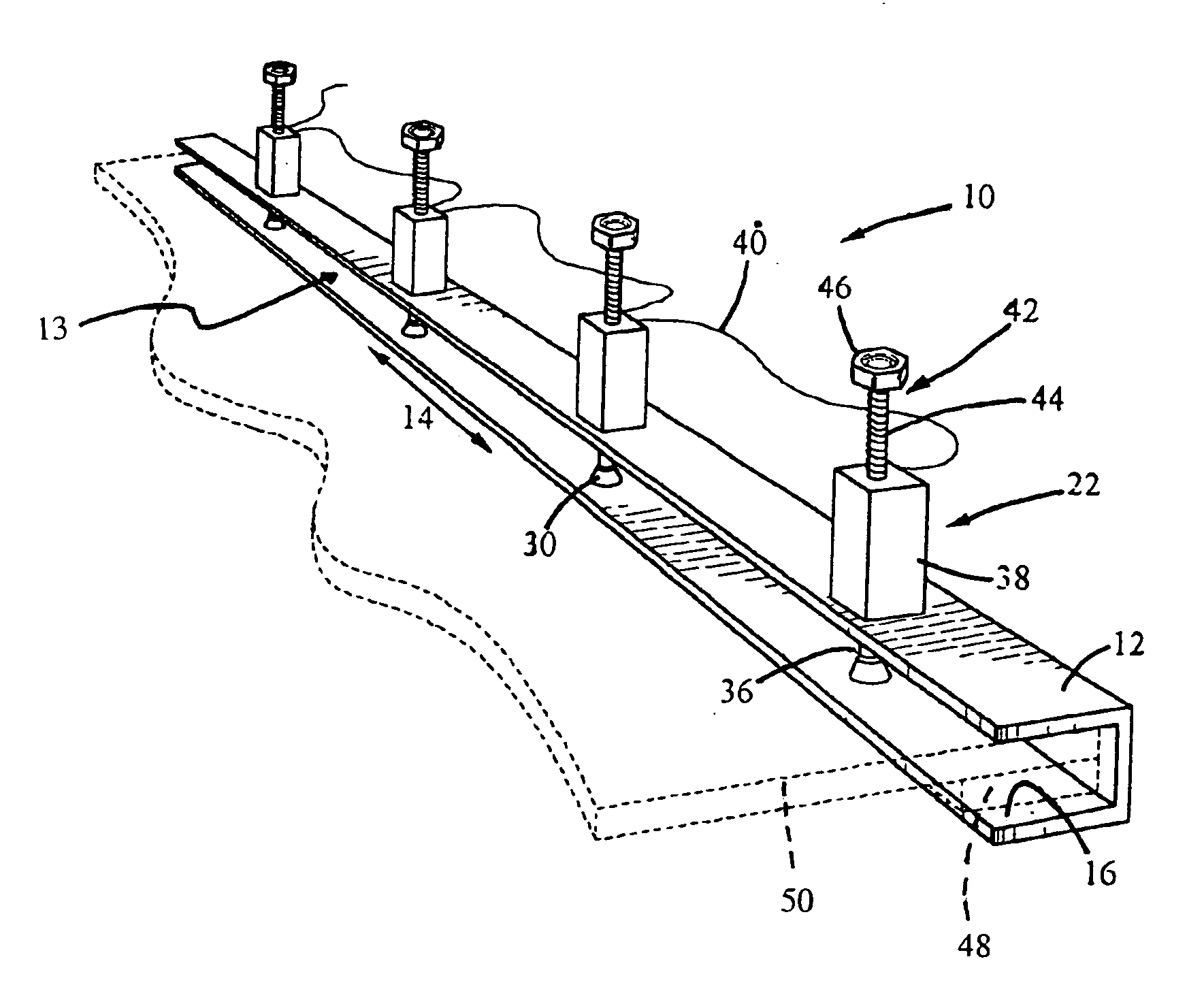
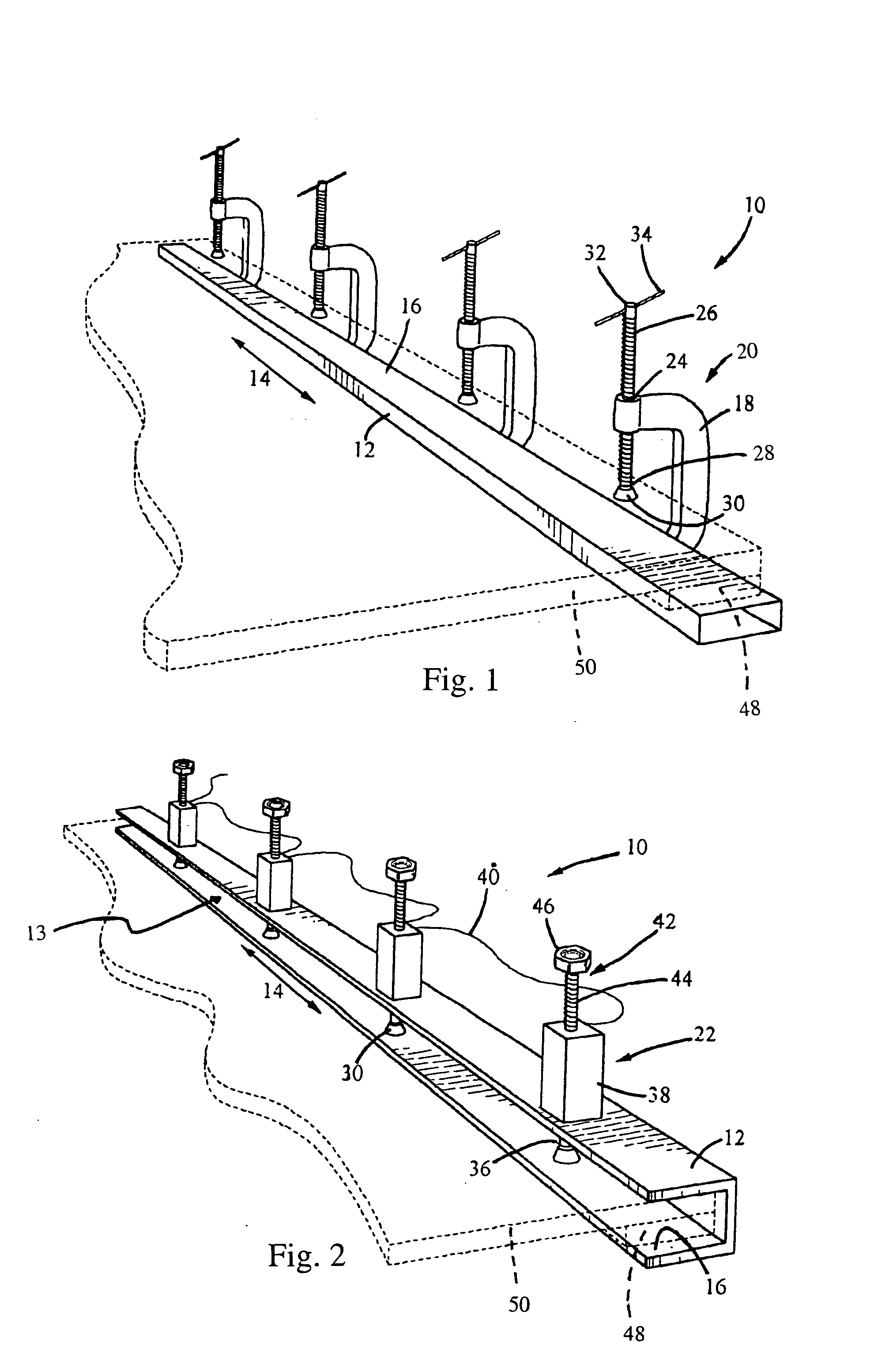
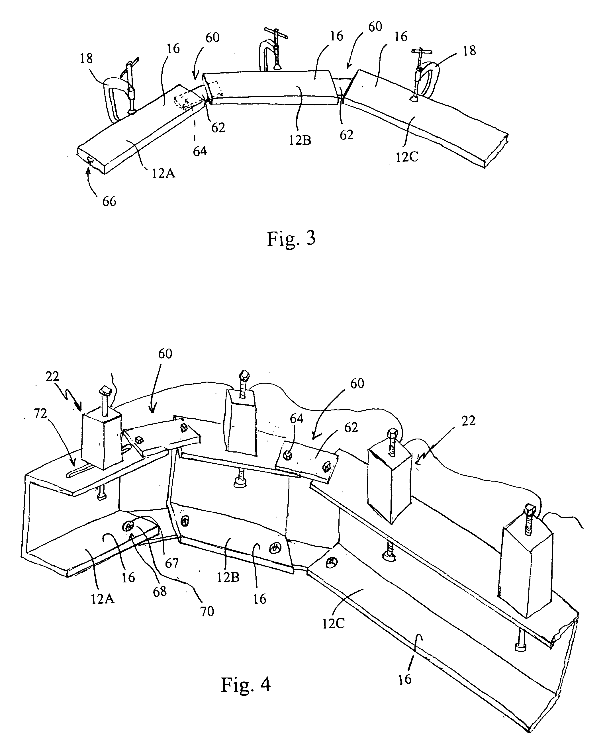
[0018] A sheet material clamp 10 includes a rigid clamp base 12 having a select length 14 and a clamping surface 16. As shown in FIG. 1 the rigid clamp base 12 can be a substantially elongate rectangular bar to which clamping structures 18 are attached at specified intervals along the rigid clamp base 12. In the alternative, as shown in FIG. 2, the rigid clamp base 12 can be fabricated as a channel member having a channel opening 13 sized to receive layered sheet material which will be clamped within the interior of the channel. As illustrated in FIGS. 1 and 2, the clamping structures are rigidly attached to the clamp base at select intervals. Alternatively, the clamping structures can be attached in a manner that enables them to slide lengthwise relative to the rigid clamp base 12. For example, each clamping structure could be mounted in a lengthwise groove in a rail on the clamp base 12, as discussed below with reference to FIGS. 3 and 4.

[0019] In either embodiment the length 14 ...


PUM


Abstract

A sheet material clamp having a rigid clamp base of a pre-selected length. The rigid clamp base has a clamping surface and at least two clamping apparatus attached to the clamping base for applying clamping pressure through a pressure foot toward the clamping surface. The apparatus for applying clamping pressure are spaced along the length of the clamp base so that clamping pressure can be applied evenly along the edge of the sheet material being clamped.

Description

RELATED APPLICATIONS [0001] This application claims priority from U.S. Provisional Patent Application Ser. No. 60 / 442,856, filed Jan. 27, 2003, entitled “Sheet Material Clamp.”BACKGROUND OF THE INVENTION [0002] 1. Technical Field [0003] The present invention is directed toward a sheet material clamp and more particularly toward a sheet material clamp with multiple clamping structures positioned lengthwise along a clamping surface. [0004] 2. Background Art [0005] It is customary in the building and construction trades to install countertops in various residential and commercial building locations such as kitchens, bathrooms or office workspaces. Relatively simple countertop designs can be fabricated offsite and installed by a finish carpenter as delivered. In the alternative, more highly specialized countertops are often fabricated from sheet materials onsite as part of the installation process. This second onsite method of installation and fabrication is typically used in more highl...

Claims


Application Information

Patent Timeline
Patent Type & Authority Applications(United States)
IPC IPC(8): B25B5/00B25B5/10
CPCB25B5/003B25B5/101B25B5/10
Inventor CROSS, CHRISTOPHER TODD
Owner CROSS CHRISTOPHER TODD
Why Eureka
Try Eureka