
Wideband dual polarized base station antenna offering optimized horizontal beam radiation patterns and variable vertical beam tilt

a dual-polarized, wideband technology, applied in the direction of polarised antenna unit combinations, individually energised antenna arrays, non-resonant long antennas, etc., can solve the problem that the optimal value of downtilt is not always predictable, and achieve the effect of improving horizontal plane radiation patterns, reducing horizontal pattern beam squint, and increasing horizontal pattern front-to-back ratio

Active Publication Date: 2005-01-06
COMMSCOPE TECH LLC
View PDF24 Cites 49 Cited by
  • Summary
  • Abstract
  • Description
  • Claims
  • Application Information

AI Technical Summary

Benefits of technology

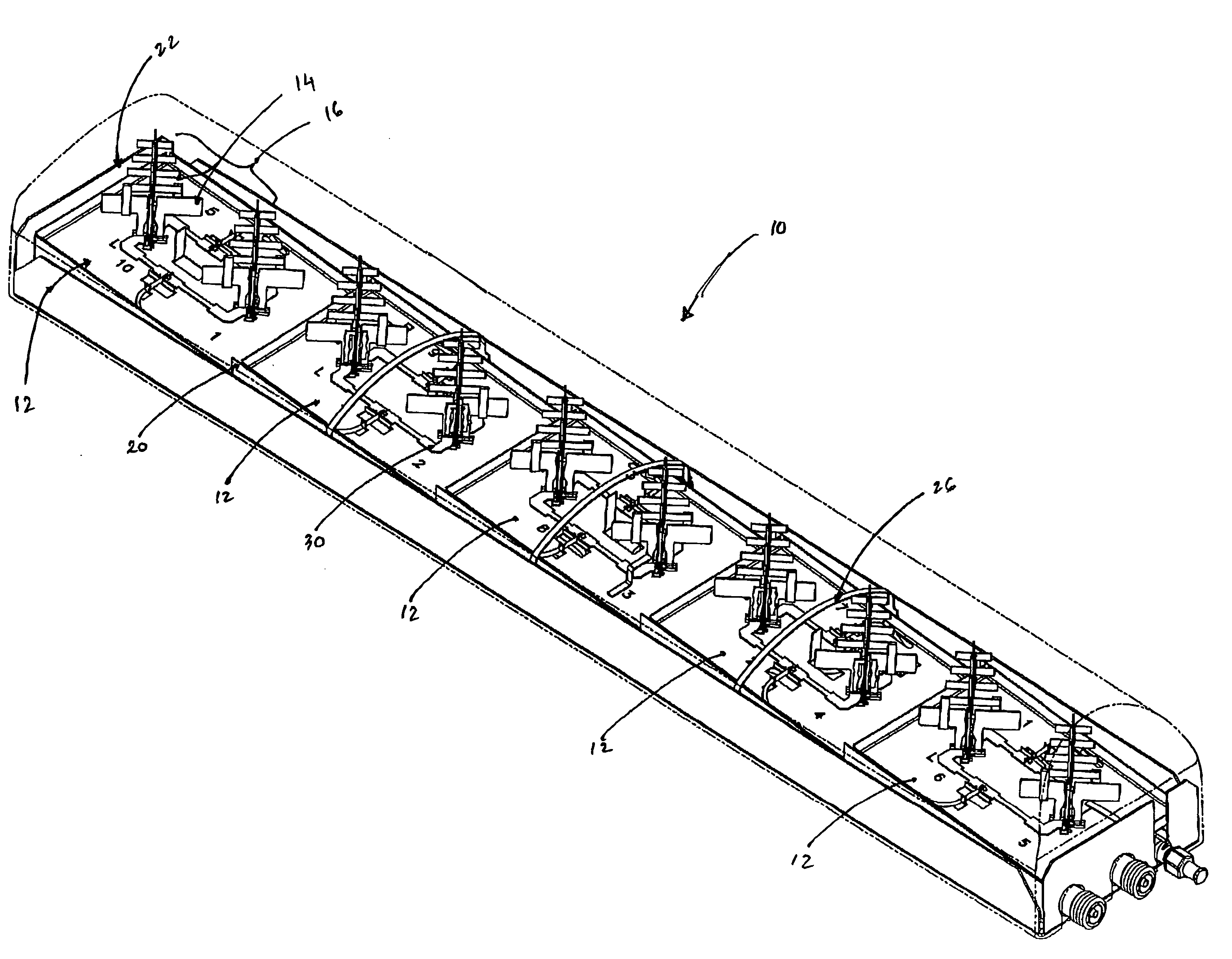
[0018] The multi-layered ground plane structure dramatically improves the horizontal plane radiation patterns. Structural features provide increased horizontal pattern front-to-back ratio, and which also reduce horizontal pattern beam squint. Specifically, the ground plane structure is composed of individual substructures that are fastened together to form a specific geometry. The substructures are preferably fabricated from either aluminum alloy, or brass alloy. Aluminum is the preferred alloy due to its high strength to weight ratio, and low cost, while brass alloy is specified in applications where electrical connections are created by soldering process. Tray supports orient the element pattern boresight at 4 degree downtilt, which is the midpoint of the array tilt range. The maximum squint level is consistent with 4 degrees downtilt off of boresight, instead of 8 degrees off of boresight. Maximum horizontal beam squint levels have been reduced to 5 degrees, which is very acceptable considering the array's operating bandwidth and tilt range.

Problems solved by technology

However, the optimum value of downtilt is not always predictable prior to actual installation and testing.

Method used


Image

  • Wideband dual polarized base station antenna offering optimized horizontal beam radiation patterns and variable vertical beam tilt
  • Wideband dual polarized base station antenna offering optimized horizontal beam radiation patterns and variable vertical beam tilt
  • Wideband dual polarized base station antenna offering optimized horizontal beam radiation patterns and variable vertical beam tilt

Examples


Embodiment Construction

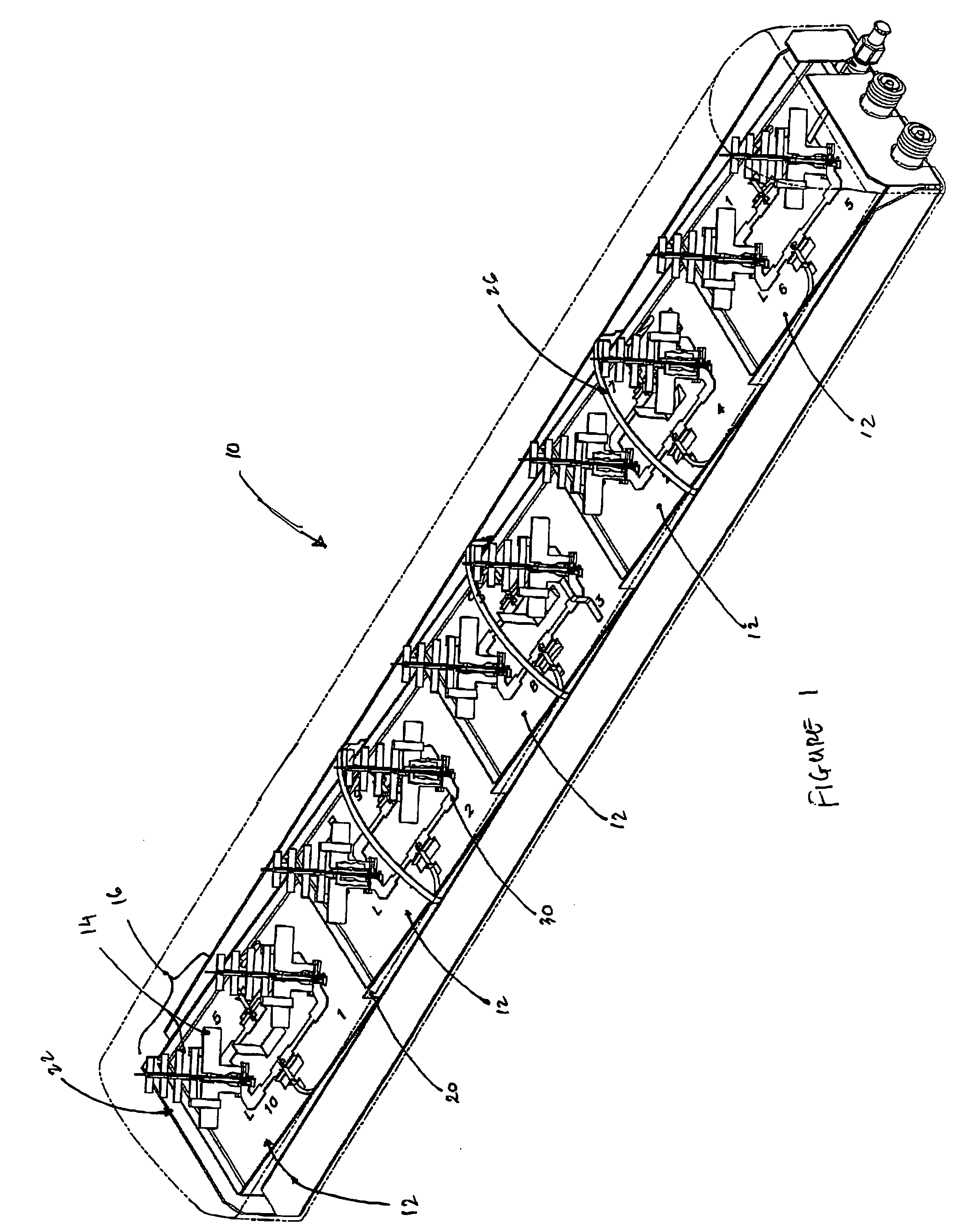
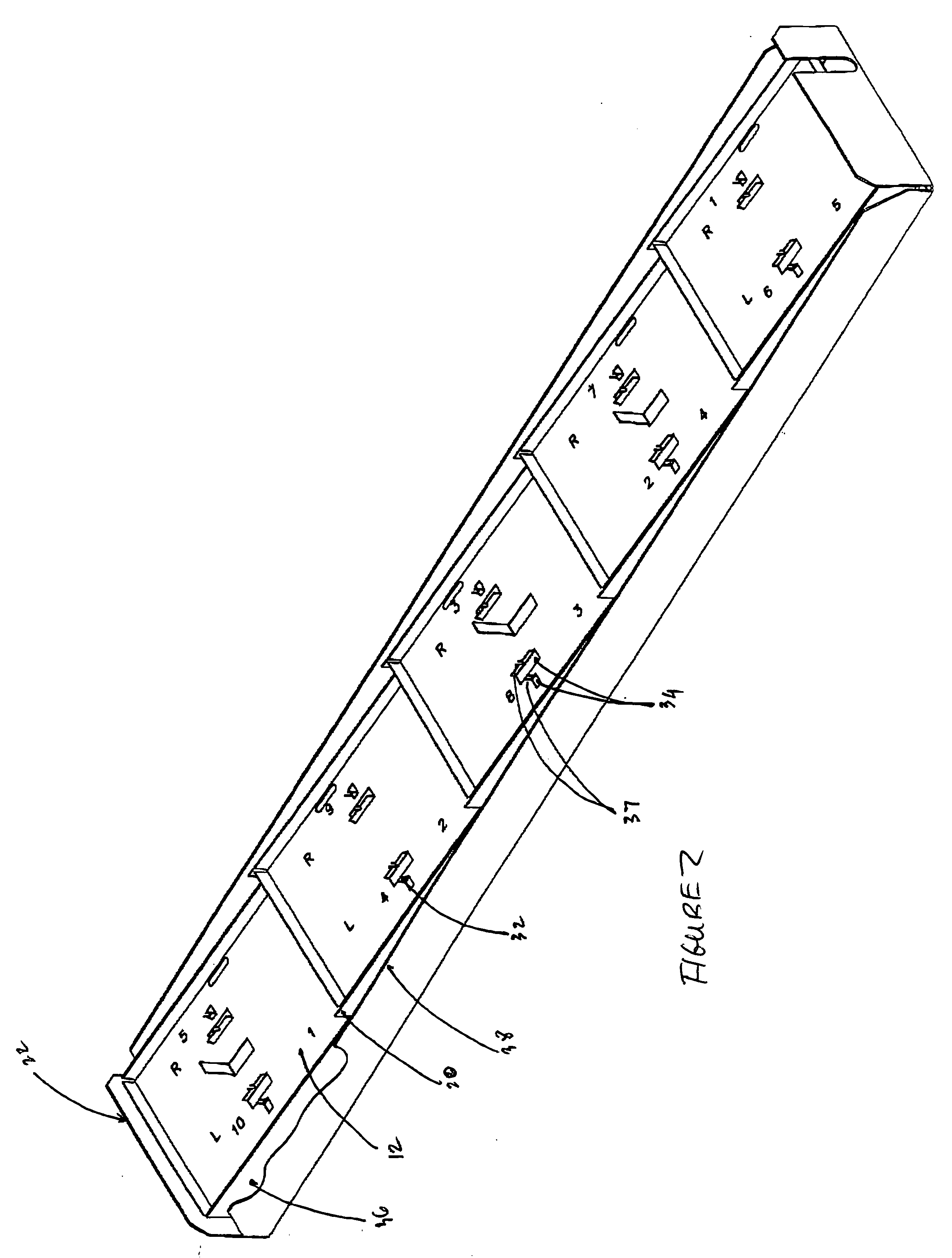
[0026] Referring now to FIG. 1, there is generally shown at 10 a wideband dual polarized base station antenna having an optimized horizontal radiation pattern and also having a variable vertical beam tilt. Antenna 10 is seen to include a plurality of element trays 12 having disposed thereon Yagi dipole antennas 14 arranged in dipole pairs 16. Each of the element trays 12 are arranged in a staircase pattern and supported by a pair of tray supports 20. The integrated element trays 12 and tray supports 20 are secured upon and within an external tray 22 such that there is a gap laterally defined between the tray supports 20 and the sidewalls of tray 22, as shown in FIG. 1 and FIG. 2. Each tray element 12 has an upper surface defining a groundplane for the respective dipole pair 16, and has a respective air dielectric feed network 30 spaced thereabove and feeding each of the dipoles 14 of pairs 16, as shown. A plurality of electrically conductive arched straps 26 are secured between the ...


PUM


Abstract

A dual polarized variable beam tilt antenna (10) having a plurality of offset element trays (12) each supporting pairs of dipole elements (14) to orient the dipole element pattern boresight at a downtilt. The maximum squint level of the antenna is a consistent downtilt off of boresight and which is at the midpoint of the antenna tilt range. The antenna provides a high roll-off radiation pattern through the use of Yagi dipole elements configured in this arrangement, having a beam front-to-side ratio exceeding 20 dB, a horizontal beam front-to-back ratio exceeding 40 dB, and is operable over an expanded frequency range.

Description

CLAIM OF PRIORITY [0001] This application claims priority of U.S. Provision patent application Ser. No. 60 / 484,688 entitled “Balun Antenna With Beam Director” filed Jul. 3, 2003, the teaching of which are incorporated herein by reference.FIELD OF THE INVENTION [0002] The present invention is related to the field of antennas, and more particularly to dual polarized base station antennas for wireless communication systems. BACKGROUND OF THE INVENTION [0003] Wireless mobile communication networks continue to be deployed and improved upon given the increased traffic demands on the networks, the expanded coverage areas for service and the new systems being deployed. Cellular type communication systems derive their name in that a plurality of antenna systems, each serving a sector or area commonly referred to as a cell, are implemented to effect coverage for a larger service area. The collective cells make up the total service area for a particular wireless communication network. [0004] S...

Claims


Application Information

Patent Timeline
IPC IPC(8): H01Q1/24H01Q3/30H01Q19/30H01Q21/08H01Q21/24
CPCH01Q1/246H01Q3/30H01Q21/24H01Q21/08H01Q19/30
Inventor LE, KEVINMEYER, LOUIS J.
Owner COMMSCOPE TECH LLC
Learn More