Fiber lasers having a complex-valued Vc-parameter for gain-guiding

a fiber laser and gain-guiding technology, applied in the field of fiber lasers, can solve the problems of insufficient gain-guiding to define guided modes, the difficulty of controlling the index of refraction in the core and cladding regions to this degree of accuracy, and the large-diameter single-mode index-guided fiber is not generally considered a practical device, etc., to achieve the effect of preventing onset, reducing gain g, and being convenient to us

Inactive Publication Date: 2004-06-15
THE BOARD OF TRUSTEES OF THE LELAND STANFORD JUNIOR UNIV
View PDF6 Cites 30 Cited by
  • Summary
  • Abstract
  • Description
  • Claims
  • Application Information

AI Technical Summary

Problems solved by technology

This is one of the major problems that need to be solved to provide single mode propagation in a multimode fiber.
Thus, the gain profile taught by the prior art is merely sufficient to perform "gain shaping" in index-guided fibers but not to determine the guided-modes.
As a practical matter, however, it is very difficult to control the index of refraction in the core and cladding regions to this degree of accuracy or to produce an accurately controlled index step this small.
Large-diameter single-mode index-guided fibers are therefore not generally considered to be practical devices.
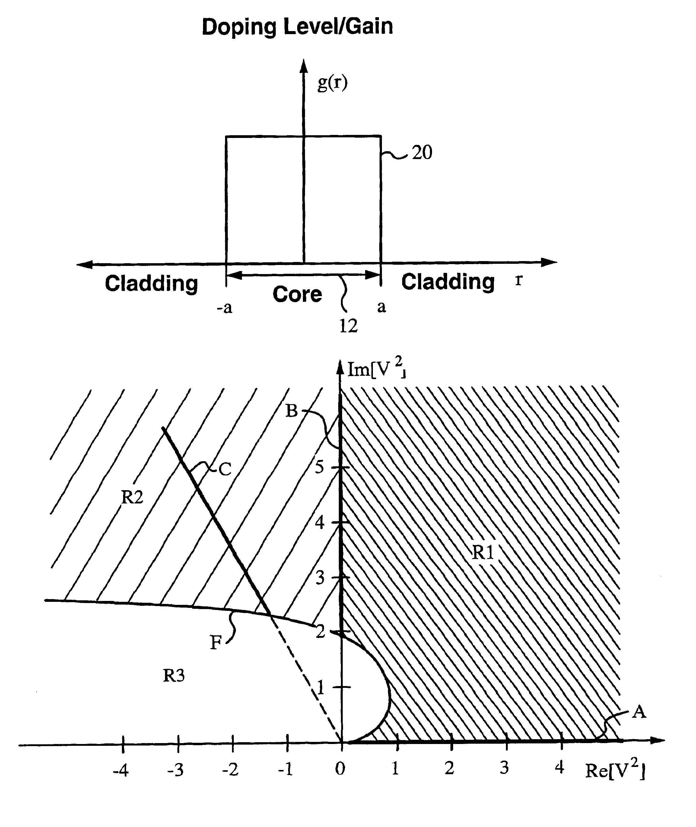
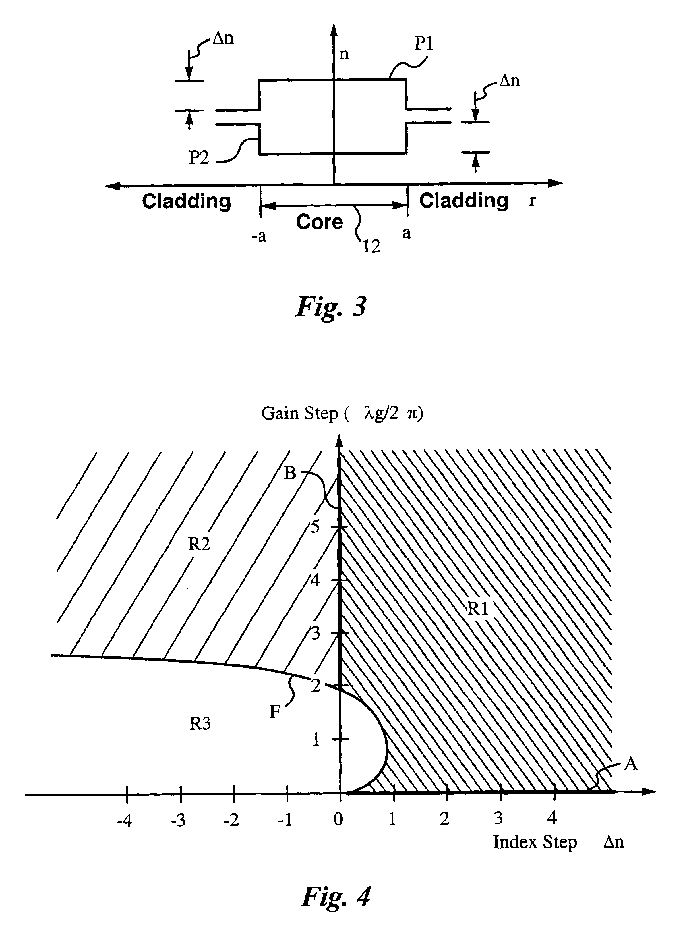
In this region the gain-guiding is not strong enough to define guided modes or overcome index anti-guiding.
In practice, it is important to bear in mind that gain-guiding is a weak effect and has poor tolerance to bending.
In general, solutions to more complex-valued doping profiles and index profiles are mathematically more challenging to derive.

Method used


Image

  • Fiber lasers having a complex-valued Vc-parameter for gain-guiding
  • Fiber lasers having a complex-valued Vc-parameter for gain-guiding
  • Fiber lasers having a complex-valued Vc-parameter for gain-guiding

Examples


example 2

FIG. 14 shows a graph of a truncated parabolic doping profile 52 with a doping diameter of 300 .mu.m produced in a fiber core of 300 .mu.m diameter. The fiber has a uniform refractive index (.DELTA.n=0). The gain has a maximum of 1 cm.sup.-1 or 4.34 dB / cm on the fiber axis. Fundamental mode 28 (TEM00) and first-order mode 30 (TEM01) are superimposed on doping profile 52. The TEM00 mode gain in this example is 2.64 dB / cm and TEM01 mode gain is 2.24 dB / cm.

example 3

FIG. 15 shows a graph of a truncated parabolic doping profile 54 with a doping diameter of 400 .mu.m produced in a fiber core of 400 .mu.m diameter. The fiber has a uniform refractive index (.DELTA.n=0). The gain has a maximum of 0.5 cm.sup.-1 or 2.2 dB / cm on the fiber axis. In this example the TEM00 mode gain is 1.8 dB / cm and TEM01 mode gain is 1.06 dB / cm.

example 4

FIG. 16 shows a graph of a step doping profile 56 with a doping diameter of 150 .mu.m produced in a fiber core of 150 .mu.m diameter. The fiber has a uniform refractive index (.DELTA.n=0) The gain has a maximum of 1 cm.sup.-1 on the fiber axis. In this example the TEM00 mode gain is 0.65 dB / cm and the percent power retained in the core is 65%.

Note that this and the following two examples represent purely gain-guided fibers that are entirely single-mode in operation, despite the large diameter of the doped core of the fiber. As shown in FIGS. 16 through 18, in each case the single mode of the fiber has a large fraction of its energy contained within the doped core, as is desirable for efficient laser operation, although the "tails" of these modes in each case have some spillover out into the cladding region of the laser.


PUM


Abstract

The instant invention concerns optical fibers that have complex-valued Vc-parameters due to gain g established by active dopants that are doped into the fiber core in accordance with a doping profile. In particular, the doping levels are very high, such that the gain g makes a sufficiently large contribution to an imaginary part of the complex-valued Vc-parameter to define at least one gain-guided mode, e.g., the fundamental mode or several low-order modes of radiation in the optical fiber. The fiber does not require any index-guiding effects to a single mode or just a few of the lowest-order modes in large cross-section cores having diameters in the range from 50 mum to 500 mum in diameter and yield kilowatt level output power. The fiber may, in addition to gain-guiding, take advantage of a refractive index profile to provide for index-guiding or index-antiguiding effects in addition to gain-guiding.

Description

This invention relates generally to coherent light sources. More particularly, it relates to high power optical fiber lasers with doping profiles selected to produce complex-valued V.sub.c -parameters to support gain-guiding of radiation.Optical fiber lasers have a core doped with ions capable of providing laser amplification when pumped with optical energy. In conventional fiber lasers, the core has a higher index of refraction than the surrounding cladding. Fiber lasers have a number of inherent advantages compared to solid state and gas lasers. Fiber lasers are simple, rugged, and inexpensive devices with a minimum of complex-valued optical and mechanical components. Optical fiber materials are compatible with a very wide range of solid state laser ions operating at many different wavelengths. These laser ions can be distributed along a substantial length of fiber, up to many meters long, with the pumping light fully trapped within the fiber over the full distance. At the same ti...

Claims


Application Information

Patent Timeline
Patent Type & Authority Patents(United States)
IPC IPC(8): G02B6/028G02B6/036G02B6/02H01S3/06H01S3/067
CPCG02B6/0285G02B6/03611G02B6/03644G02B6/03694H01S3/067H01S3/06716H01S3/094007
Inventor SIEGMAN, ANTHONY E.
Owner THE BOARD OF TRUSTEES OF THE LELAND STANFORD JUNIOR UNIV
Why Eureka
Try Eureka