Image recording method and image recording device

a recording method and image technology, applied in the field of image recording method and image recording device, can solve the problems of optical magnification variation in the magnification of the optical system

Inactive Publication Date: 2005-01-06
ADTEC ENG +1
View PDF11 Cites 13 Cited by
  • Summary
  • Abstract
  • Description
  • Claims
  • Application Information

AI Technical Summary

Benefits of technology

[0012] In view of the aforementioned, an object of the present invention is to provide an image recording method and an image recording device in which, in a case in which an image is recorded by a recording head which is structured by lining-up a plurality of recording element units in a direction intersecting a scanning direction, even if errors in the optical magnifications of the respective recording element units arise, offset of the image recording positions can be corrected without using a mechanical adjusting mechanism.
[0018] In this way, an adjusting mechanism which mechanically adjusts the positions of the recording element units or the like is not needed, and even if there are fluctuations in the optical magnifications, positional offset does not arise.
[0027] In this way, an adjusting mechanism which mechanically adjusts the positions of the recording element units or the like is not needed, and even if there are fluctuations in the optical magnifications, positional offset does not arise.

Problems solved by technology

Therefore, there are cases in which the magnifications of the optical systems (the optical magnifications) vary due to physical differences (e.g. instrumental errors) among the optical systems or the assembled states thereof, or the environmental temperature or humidity or the like.

Method used


Image

  • Image recording method and image recording device
  • Image recording method and image recording device
  • Image recording method and image recording device

Examples


Embodiment Construction

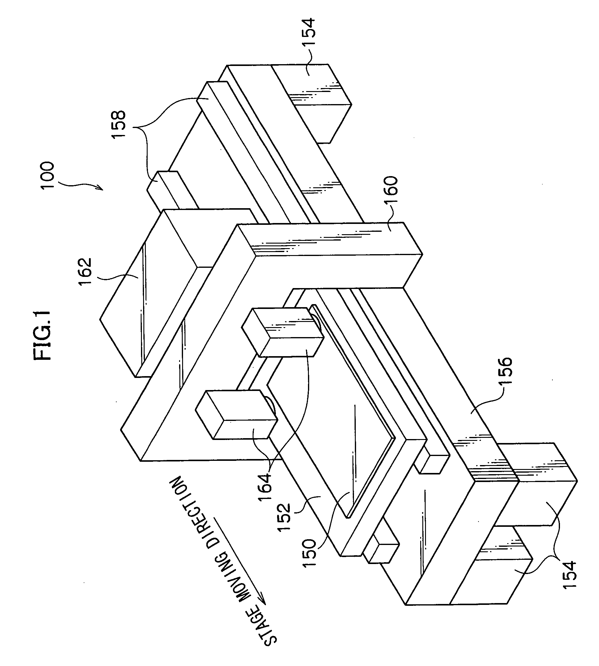
[0037] A flatbed-type image recording device 100 relating to the present embodiment is shown in FIG. 1.

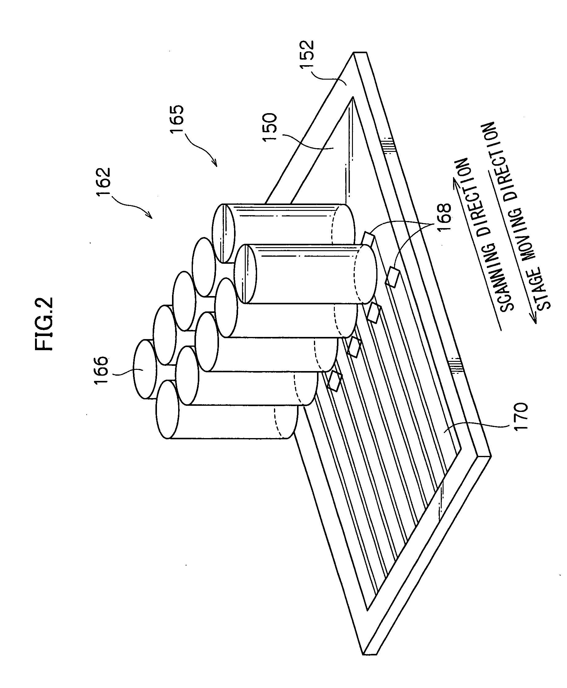
[0038] The image recording device 100 has a setting stand 156 which is shaped as a thick plate and which is supported by four leg portions 154. Further, the image recording device 100 has a flat-plate-shaped stage 152 disposed via two guides 158 which extend along the stage moving direction. The stage 152 functions to suck and hold a sheet-shaped photosensitive material 150 to the surface of the stage 152.

[0039] The longitudinal direction of the stage 152 is the stage moving direction. The stage 152 is guided by the guides 158, and is supported so as to be reciprocatingly movable (scannable). Note that an unillustrated driving device for driving the stage 152 along the guides 158 is provided at the exposure device 100. Driving control is carried out by an unillustrated controller such that the stage 152 moves at a moving speed (scanning speed) corresponding to a desired magnifica...


PUM


Abstract

An image recording method of recording an image onto an image recording surface by dot patterns by scanning a recording head having recording element units arranged in a direction intersecting a scanning direction, the recording element units having a light source and an optical system which receives light from the light source, forms light beams which are arranged two-dimensionally, and focuses the light beams on the image recording surface. The method includes: measuring displacement amounts of positions of light beam spots on the image recording surface generated due to a change in optical magnification of the optical system; changing a light-emitting timing at a time of start of scanning in the scanning direction, on the basis of a displacement amount in the scanning direction; and changing a resolution in the direction intersecting the scanning direction, on the basis of a displacement amount in the direction intersecting the scanning direction.

Description

CROSS-REFERENCE TO RELATED APPLICATION [0001] This application claims priority under 35 USC 119 from Japanese Patent Application No. 2003-190432, the disclosure of which is incorporated by reference herein. BACKGROUND OF THE INVENTION [0002] 1. Field of the Invention [0003] The present invention relates to an image recording method and an image recording device which record an image on an image recording surface. More specifically, the present invention relates to an image recording method and an image recording device which record an image onto an image recording surface by dot patterns, by scanning, along the image recording surface, a recording head which is structured such that a plurality of recording element units are arranged in a direction intersecting a scanning direction. [0004] 2. Description of the Related Art [0005] Conventionally, various image recording devices have been proposed which record an image onto a recording medium by using a recording head which irradiates ...

Claims


Application Information

Patent Timeline
Patent Type & Authority Applications(United States)
IPC IPC(8): B41J2/44B41J2/45B41J2/455B41J2/465G03G15/04H04N1/23
CPCB41J2/465G03F7/2053G03G15/0415B41J2/455B41J2/5056
Inventor UEMURA, TAKAYUKINAKAYA, DAISUKEFUJII, TAKESHI
Owner ADTEC ENG
Why Eureka
Try Eureka