Catchable plug

Inactive Publication Date: 2005-01-06
LAPPOHN JURGEN
View PDF2 Cites 5 Cited by
  • Summary
  • Abstract
  • Description
  • Claims
  • Application Information

AI Technical Summary

Benefits of technology

[0015] In another embodiment of the invention, the SMD contact surfaces are formed on attachment devices to solder these attachment devices and also the entire plug onto a circuit board. However, press-in zones can also be formed in this attachment device. To assure an alignment of this plug relative to a circuit board, one of these

Problems solved by technology

This results in a significant increase in the number of components of

Method used


Image

  • Catchable plug
  • Catchable plug
  • Catchable plug

Examples


Example

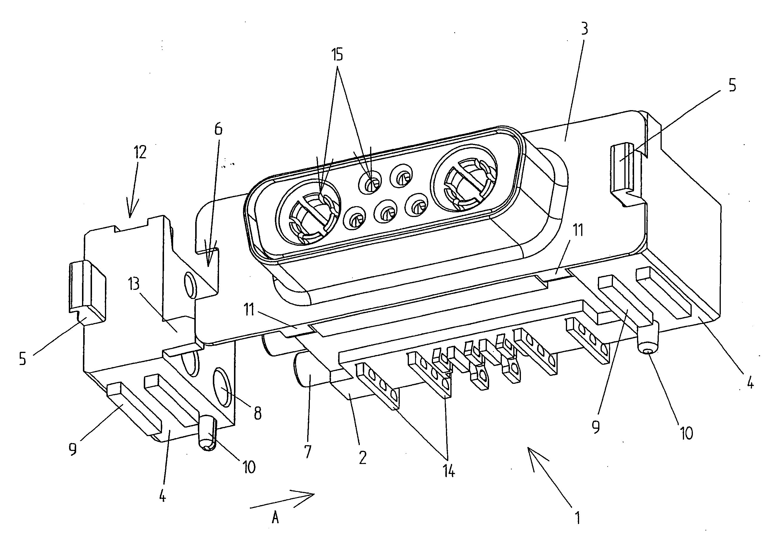
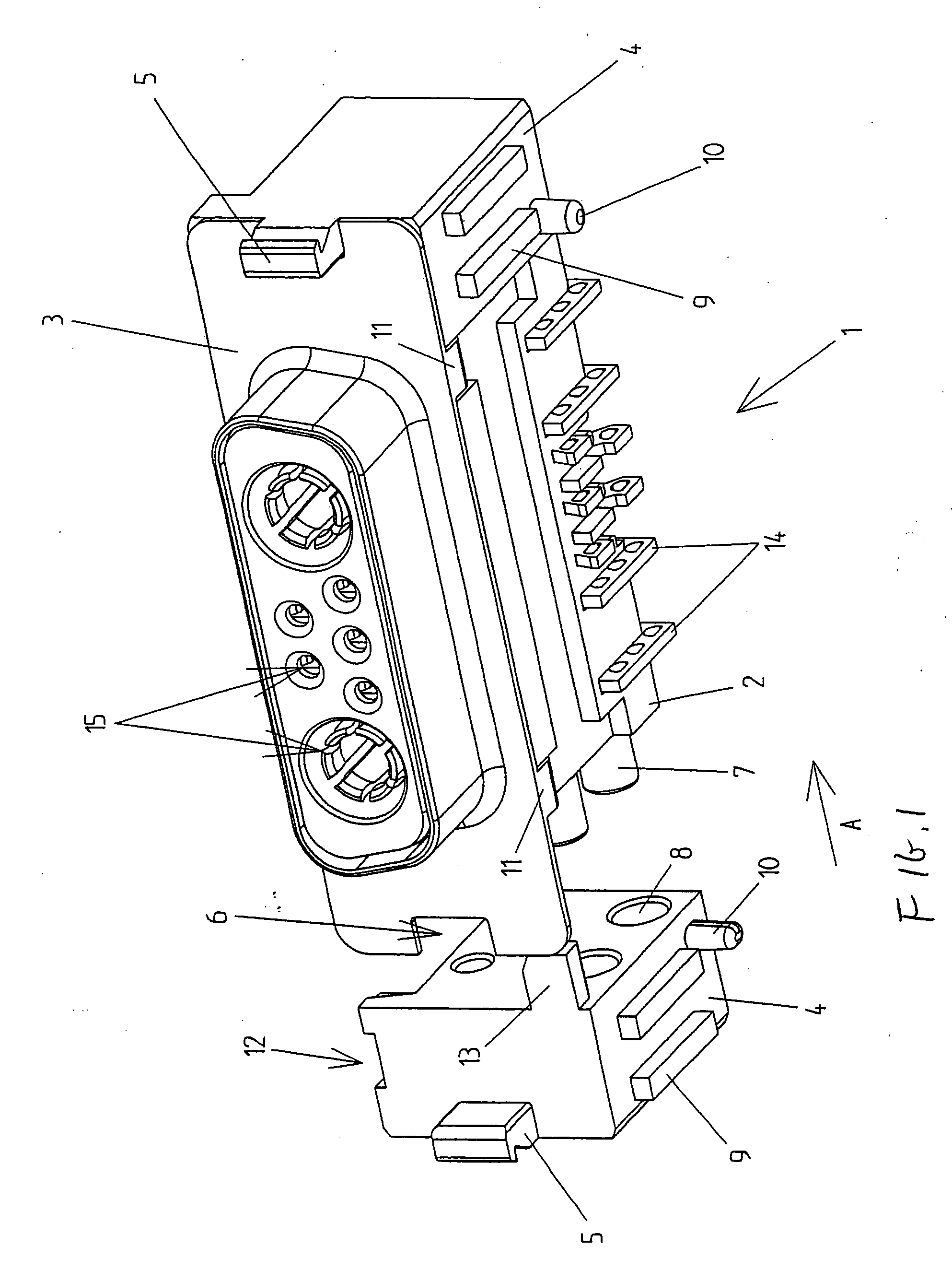
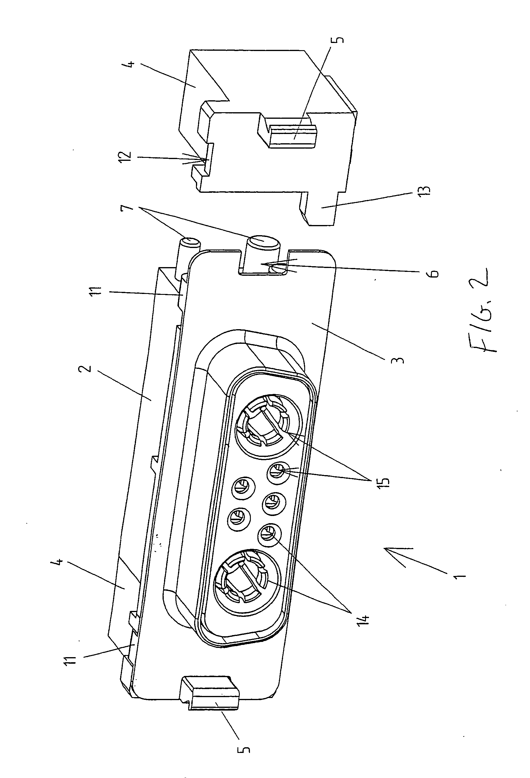
[0026] Referring to the drawings, FIG. 1 to 4 show various respective views of the invention wherein there is shown a plug 1 which has a plug housing 2, which is formed from a plastic injection molded part. Plug 1 has a shielding plate 3 made from metal which rests against a front of the plug housing 2 essentially formed in its entire area as a flat area that covers the shielding plate. There are passage openings that are used to accommodate electrical or optical contacts which are formed in the plug housing. In this case, the contacts 14 can be set into plug housing 2 in a known manner and locked in place in this plug housing if necessary.

[0027] Electrical or optical signals are transmitted from one electrical or optical element to another using plugs 1. In this case, electrically conductive connections can be produced using these contacts 14. Plugs 1 are attached to circuit boards using two symmetrical attachment devices 2 wherein this attachment takes place by pressing known pre...


PUM


Abstract

A plug having a plug housing and a shielding plate. The plug is fixed in place on a circuit board with at least one attachment device. This attachment device can be attached to the plug housing. To attach the plug to another component, there is a catch element formed on the attachment device which passes through a corresponding recess in said shielding plate in the plug.

Description

CROSS REFERENCE TO RELATED APPLICATIONS [0001] This application hereby claims priority from German application serial no. DE 10329894.0 filed on Jul. 3, 2003 wherein priority is hereby claimed under 35 U.S.C. 119. BACKGROUND OF THE INVENTION [0002] A catchable plug wherein the plug can be in the form of a plug element wherein an optical contact can be produced between the plug and a plug that is configured to be complementary to it. The term plug can be understood to mean all plug connection elements such as plugs, plug connectors, male and female multipoint plugs, wherein electrical contacts can be produced between the plug and a plug that is configured to be complementary to it. Using these plugs, electrical or optical components can be used for transmitting signals or energy between different electrical or optical components. [0003] Other attachment devices are known in the art. For example, DE 102 43 407 involves contacts on circuit boards, boards motherboards, backplanes or sim...

Claims


Application Information

Patent Timeline
IPC IPC(8): H01R13/627H01R13/658H01R13/73
CPCH01R12/57H01R13/6275H01R13/6588H01R12/707H01R12/7052
Inventor LAPPOHN, JURGEN
Owner LAPPOHN JURGEN
Why Eureka
Try Eureka