
Endoscope shaft

Active Publication Date: 2005-01-06
INVENDO MEDICAL
View PDF11 Cites 20 Cited by
  • Summary
  • Abstract
  • Description
  • Claims
  • Application Information

AI Technical Summary

Benefits of technology

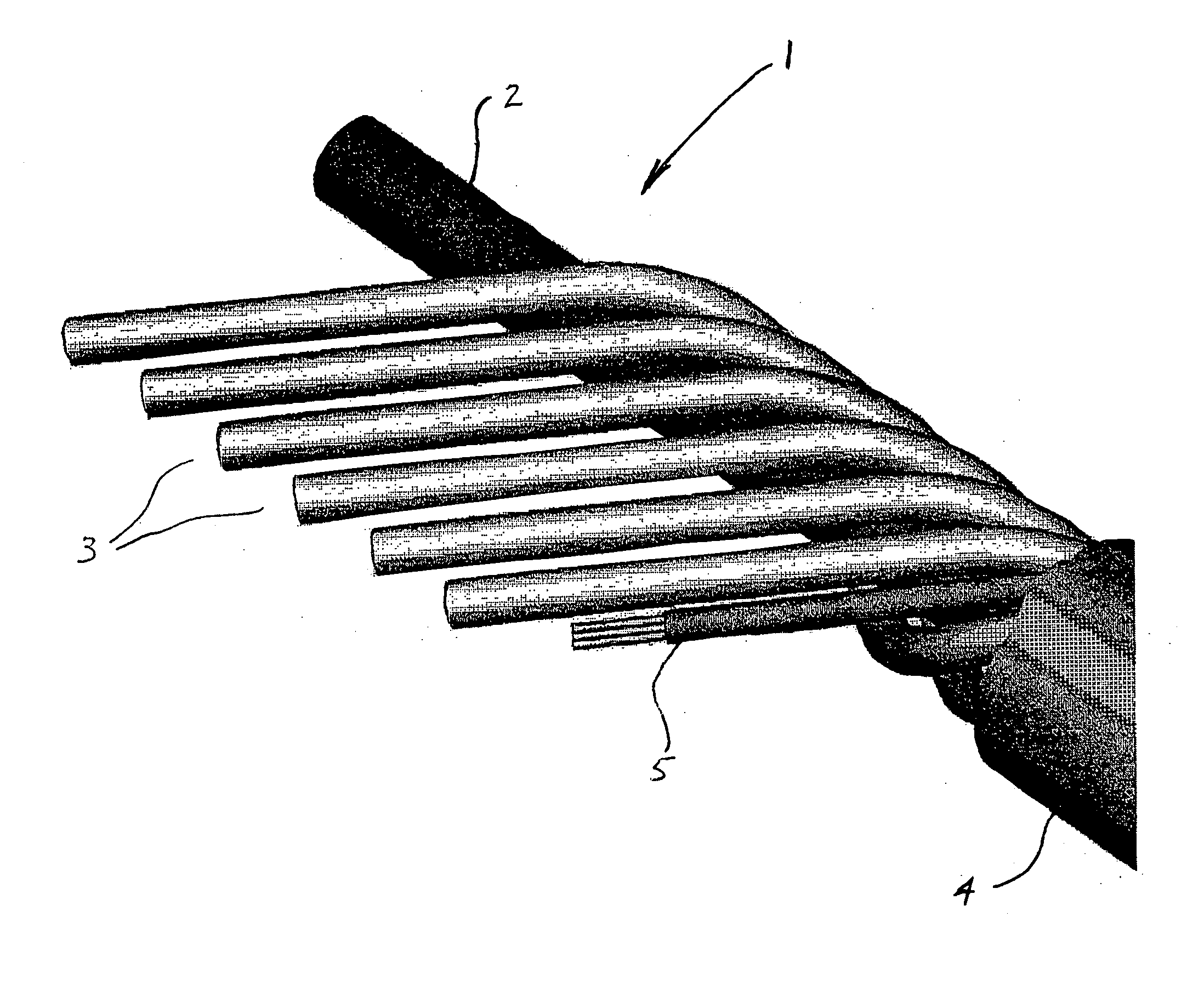
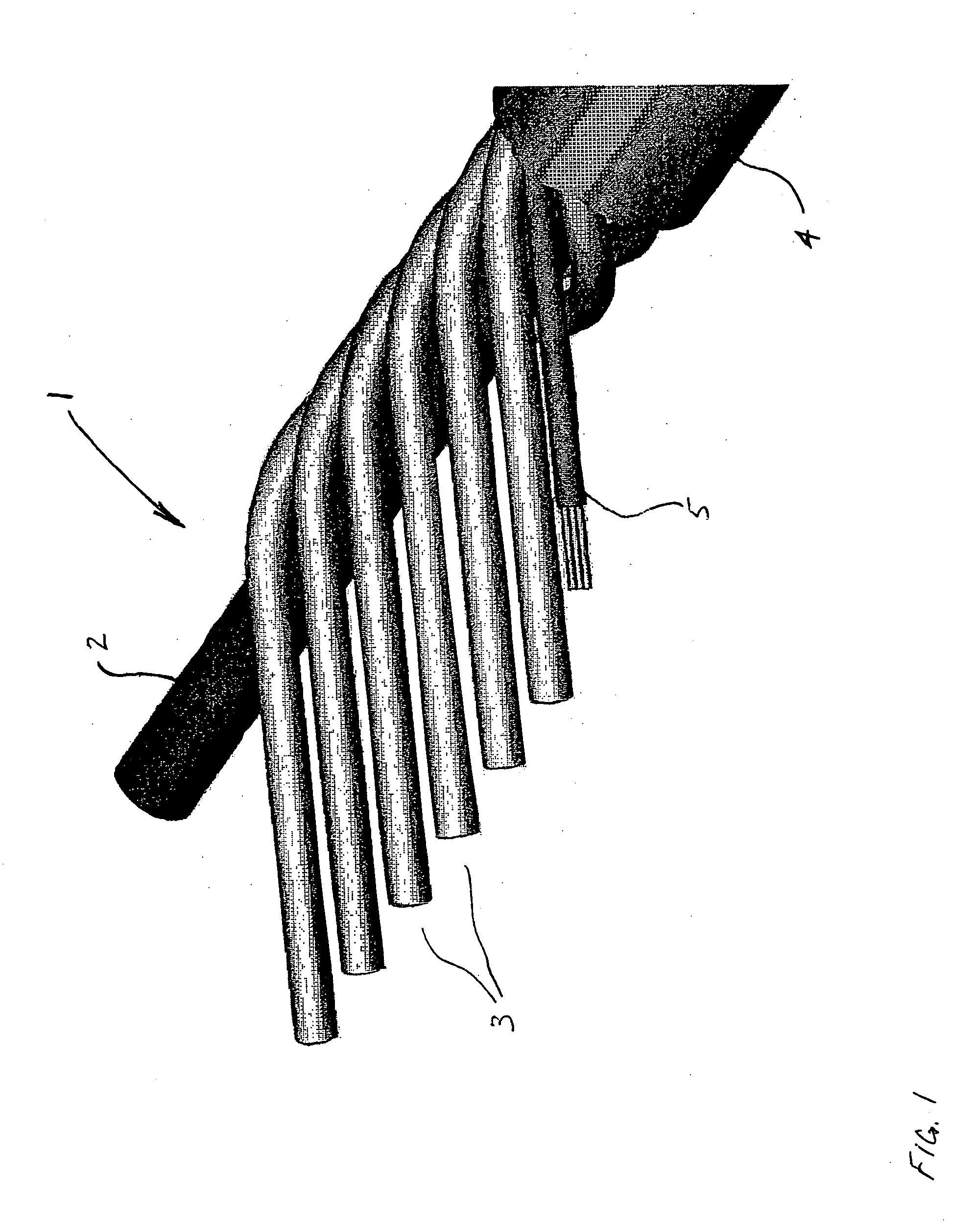
[0009] In principle, this is achieved by the fact that the conduits have an excessive length with respect to the endoscope shaft. In this way, the bending behavior is less impaired by the supply and / or functional conduits. Moreover, the endoscope shaft can now be bent without giving rise to the risk that the conduit walls start to tear.
[0010] In an advantageous manner, the supply and / or functional conduit(s) which is / are usually located eccentrically in the endoscope shaft is / are arranged according to the invention to extend spirally around the working conduit or in serpentine or zigzag shape in the longitudinal direction of the endoscope shaft or in a combination of these measures. In this way, the flexibility of the endoscope shaft is less dependent on the characteristics of the materials used for the conduits, but the flexibility is obtained by the shaping and arrangement of the conduits as a helix according to the invention. By this design, bending diameters of less than 30 mm can be achieved without a break-up of the conduit walls occurring.
[0013] It has also turned out to be advantageous to manufacture the endoscope shaft of synthetic resin foam in which the supply and functional conduits are embedded or formed. Such foam material forms on its surface, i.e. the surface shell of the endoscope shaft, pores, indentations and similar surface depression which, when bending the endoscope shaft, cause a bellows effect, that is they reduce the surface tension due to pulling apart or folding up surface folds.

Problems solved by technology

In principle, this is achieved by the fact that the conduits have an excessive length with respect to the endoscope shaft.

Method used


Image

  • Endoscope shaft
  • Endoscope shaft
  • Endoscope shaft

Examples


first embodiment

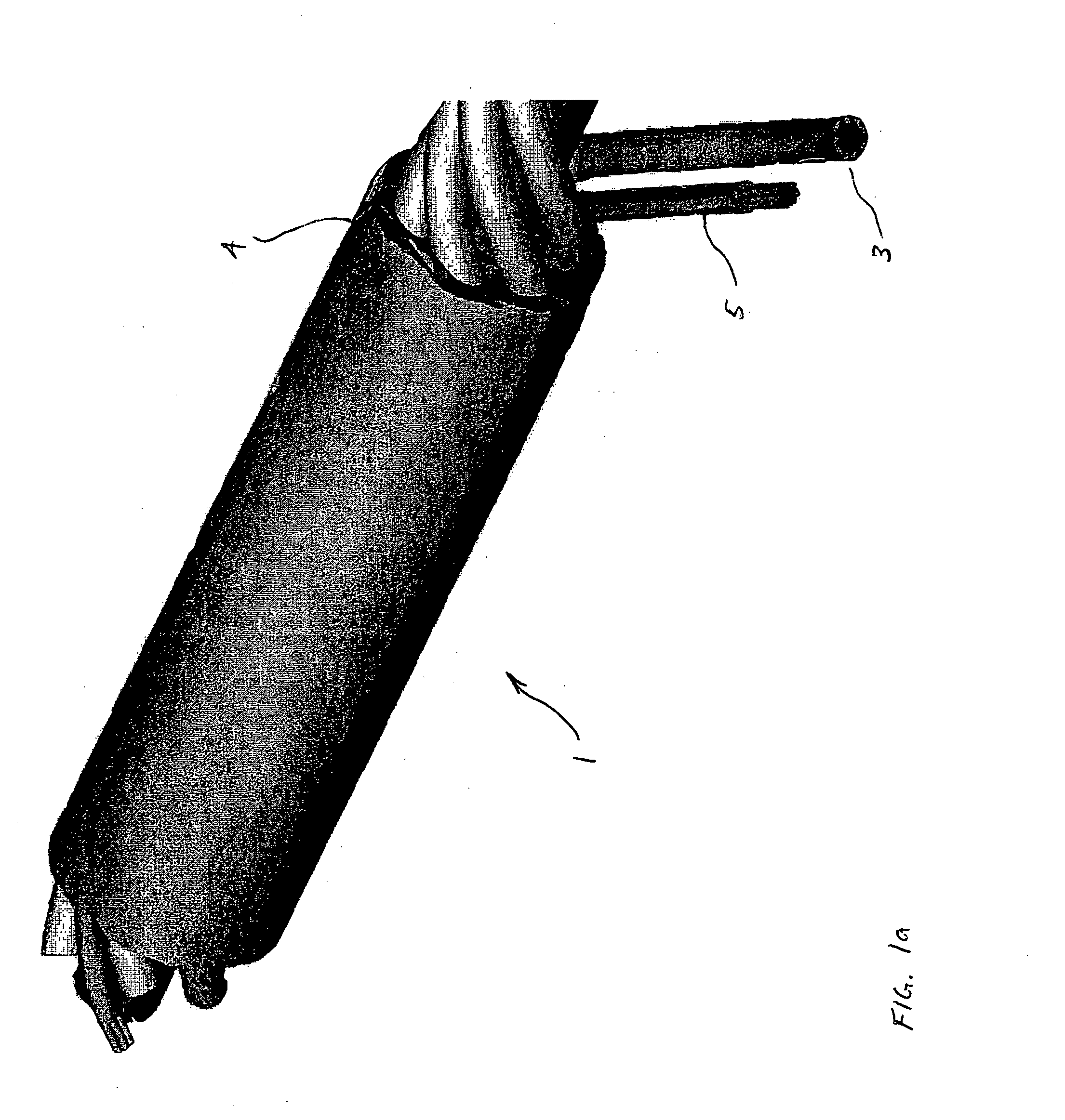
[0026] According to FIG. 1, the working conduit 2 is formed in this first embodiment by a flexible tube or hose, preferably of a plastic material, around which an envelope 4 preferably of synthetic resin foam is shaped. As one can take from FIG. 1a, in this envelope 4 the supply and / or functional conduits 3 are embedded and are wound individually at a predetermined parallel distance from each other as well as preferably in an angular symmetry around the working conduit 2 to form a spiral having a defined gradient. There is moreover provided a fiber or cable bundle 5 which is spirally guided in parallel to the supply and / or functional conduits 3 likewise around the working conduit 2 and is embedded in the envelope 4. The supply and / or functional conduits 3 and the cable bundle 5 are arranged at a predetermined radial distance from the working conduit 2, however, so that they are completely enclosed by the envelope material. This guarantees that the inner wall of the working conduit 2...

second embodiment

[0029] As one can take especially from FIG. 2, the conduits 3 are manufactured of tubes preferably of a plastic material which are then enclosed by a further synthetic envelope, preferably synthetic resin foam, which is shaped into the flat strip section and connects the tubes to form a unit. In the second embodiment, the cables or fibers 5 are arranged individually or in thin fiber bundles (including few fibers) between the tubes in the envelope material. This separation of the fibers / cables 5 increases the flexibility of the flat strip 6 and simultaneously improves the homogeneity of the same.

[0030] The flat strip spiral preformed in this way is subsequently glued or welded at the respective longitudinal edges 8, thus forming the radially closed working conduit 2, as this is shown in FIG. 3 The longitudinal edges 8 may be either butt-welded / glued or may slightly overlap, to which purpose in the latter case the flat strip edges 8 are thinned in the overlapping area so as to avoid m...

fourth embodiment

[0033]FIGS. 5, 5b show a fourth embodiment for the arrangement of a supply and / or functional conduit.

[0034] In accordance with the fourth embodiment of the invention, the supply and / or functional conduits 3 are arranged radially with respect to each other in a kind of hose package 9, wherein the cables or fibers 5 are preferably located at equal angular distances from each other at the outsides of the hose package 9. The hose package 9 consists of an extruded or foamed synthetic rope forming the conduits 3 themselves which in the present case are shaped into quarter circles in their cross-section.

[0035] At this point, it shall be pointed out that also a number of supply and / or functional conduits different from four conduits according to the fourth embodiment may be provided. Also, the hose package is guided spirally around the working conduit, as is shown in the first to third embodiments.


PUM


Abstract

An endoscope shaft comprising a working conduit and a number of supply and / or functional conduits. The supply and / or functional conduits have an excessive length with respect to the endoscope shaft and are arranged in spirals, in serpentine and / or zigzag shape around or along the working conduit, whereby a flexibility and bendability of the endoscope shaft is achieved.

Description

BACKGROUND OF THE INVENTION [0001] The present invention relates to an endoscope shaft. [0002] Endoscopes are instruments especially for exploring cavities or tube-shaped canals of the body, for instance for medical purposes. Endoscopes of this kind are preferably used for exploring the gullet, the stomach, the duodenum from the stomach, the intestine from the anus, the urethra, the vesica and the ureter. Endoscopes are mostly equipped with a lighting device at their front end and with an optical system for visually detecting the area of the body cavity or body canal located forward thereof. [0003] Further, endoscopes usually comprise a working conduit, as it is called, through which various working instruments can be introduced and operated, e.g. forceps for taking tissue samples, biopsy needles, heatable cutting wires, small scissors or the like. Finally, as a rule, functional conduits, for instance a fluid conduit for wash and operating wires for bending the front end of the endo...

Claims


Application Information

Patent Timeline
IPC IPC(8): A61B1/00G02B23/24A61B1/012A61B17/34
CPCA61B1/0055A61B2017/3445A61B17/3421A61B1/012
Inventor BOB, KONSTANTINKAST, WOLFGANG
Owner INVENDO MEDICAL
Learn More