
Drug infusion device with tissue identification using pressure sensing

a tissue identification and drug technology, applied in the field of drug infusion device with tissue identification using pressure sensing, system for subcutaneous injection/aspiration, can solve the problems of pain and tissue damage, failure of medical objectives, and inability to provide a means for drug delivery or aspiration subcutaneously

Inactive Publication Date: 2005-01-06
MILESTONE SCIENTIFIC INC
View PDF2 Cites 77 Cited by
  • Summary
  • Abstract
  • Description
  • Claims
  • Application Information

AI Technical Summary

Benefits of technology

[0015] The present invention provides a method and device that enables the practitioner to utilize a diagnostic and therapeutic device simultaneously. The current device utilizes the inherent tissue density or resistance of fluid pressure within that tissue to identify the accuracy of placement of a needle within specific tissues. Each tissue has its own pressure density characteristics which are represented as measurable pressures that can be elicited within a given tissue type. The density or resistance of the tissue is measured using the pressure/force of a fluid infused from a computer-controlled d

Problems solved by technology

However, these systems do not provide a means for drug delivery or aspiration subcutaneously via a hypodermic needle.
Accurately positioning a hollow-bore needle within tissues to delivery medication within tissue structures has long been a challenge in both medicine and dentistry.
The inability to accurately position a hollow-bore needle within specific tissues (i.e. soft-tissues) or organs can lead to a failed medical objective.
The pain and tissue damage are a direct result of uncontrolled flow rate in conjunction with excessive pressures created during the administration of drug solutions within the tissue spaces.
Also, it has been scientifically demonstrated that particular pressures (excessive without occlusion, per se) for a specific tissue type will cause damage.
However, the patent does not address the problem of identifying the tissue in which an injection is being made.
A major deficiency of these systems is their inability to adjust the flow rate and / or pressure of the fluid to compensate for changes in resistances throughout the system, or to the exit pressure.
Moreover, the prior art references fail to provide any means of determining this exit pressure.

Method used


Image

  • Drug infusion device with tissue identification using pressure sensing
  • Drug infusion device with tissue identification using pressure sensing
  • Drug infusion device with tissue identification using pressure sensing

Examples


Embodiment Construction

[0035] The subject invention pertains to a system for delivering drugs such as an anesthetic, under pressure into a patient's tissues. Importantly, due to a variety of factors, injected fluid disperses through a tissue at different rates, causing the fluid exit pressure to vary. The present inventor has discovered that this exit pressure (or an internal pressure related to the exit pressure) is indicative of, and may be used to identify several types of tissues.

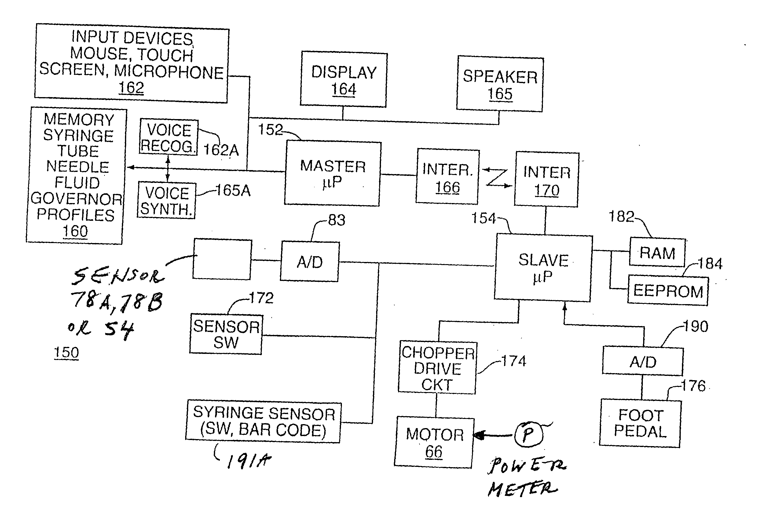
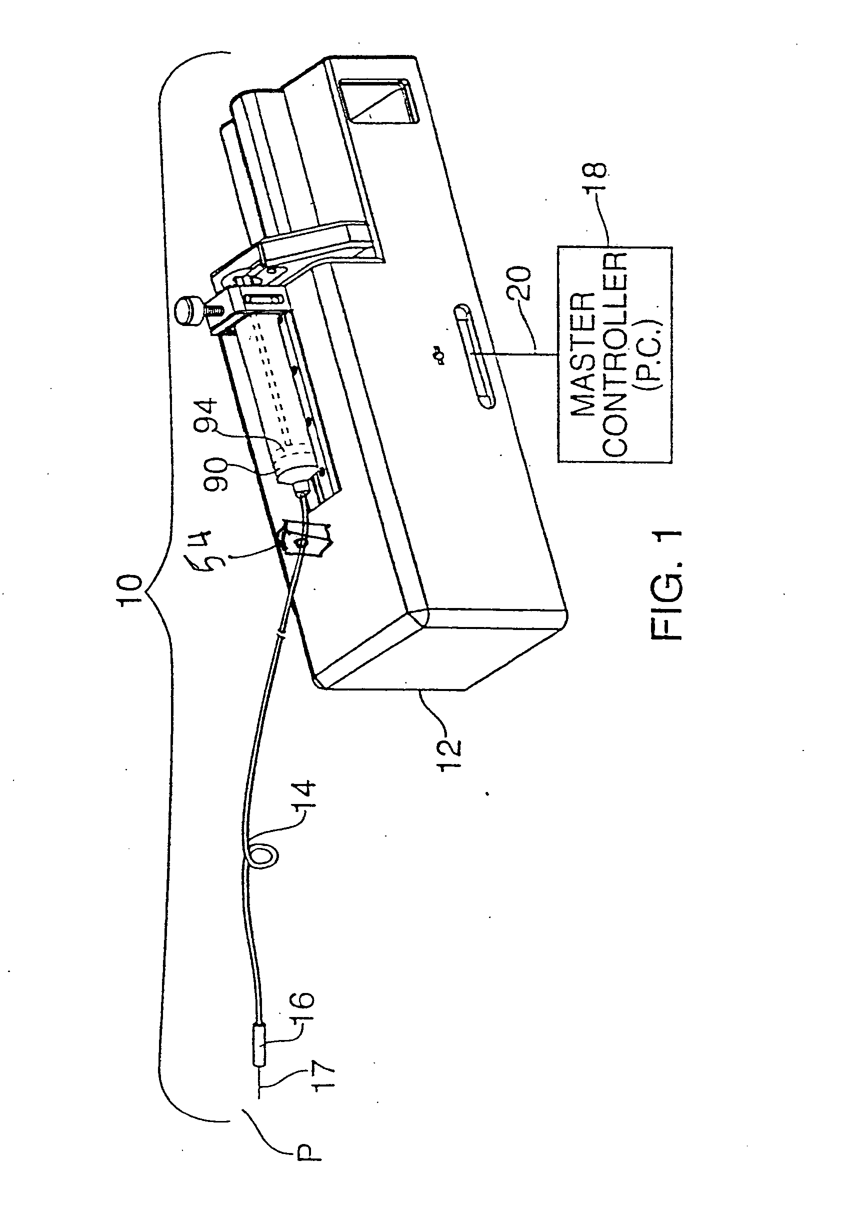
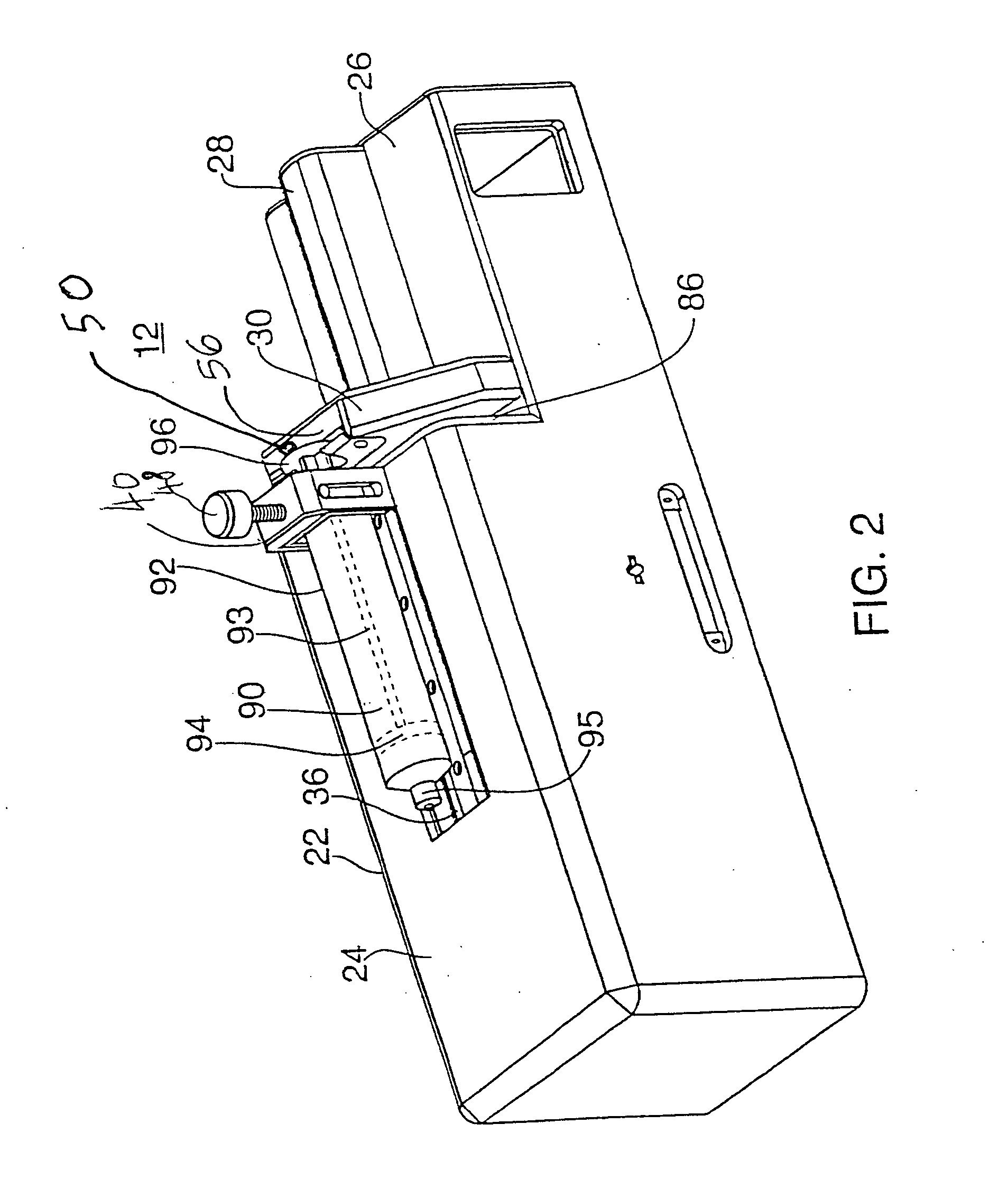
[0036] The mechanical assembly for the subject system is illustrated in FIGS. 1 and 2 and the electronic controller 150 for the system is shown in FIG. 3.

[0037] A drug delivery system 10 constructed in accordance with this invention includes drive mechanism 12, a delivery tube 14 and a handle 16 terminating with a needle 17. More particularly, a syringe 90 (or other fluid storage device) is mounted on the drive mechanism with one end of tube 14 being coupled to the syringe 90. The drive mechanism 12 operates a plunger 94 to...


PUM


Abstract

An automatic injection device includes a drive mechanism and a sensor used to determine an internal characteristic such as a force or internal pressure generated during an injection process. This characteristic is then used as a control parameter by a microprocessor or controller to determine the exit pressure of the fluid expelled by the device. This exit pressure is then used to identify the kind of tissue in which the injection is being introduced.

Description

RELATED APPLICATION [0001] This application claims priority to U. S. Provisional application Ser. No. 60 / 502,379 filed Sep. 12, 2003 and incorporated herein by reference. [0002] This application is also a continuation in part application to application Ser. No. 09 / 766,772 filed Jan. 22, 2001, which is a divisional of application Ser. No. 9 / 201,464 filed Nov. 30, 1998 claiming priority to provisional application Ser. No. 60 / 081,388 filed Apr. 10, 1998, all incorporated herein by reference.BACKGROUND OF THE INVENTION [0003] a. Field of Invention [0004] The present invention relates generally to improvements to the delivery of drugs, particularly to systems for subcutaneous injection / aspiration. More specifically this invention provides a method and device to the identification of specific tissue types (or soft-tissue density types) based on using a pressure measurement. [0005] b. Description of the Prior Art [0006] Infusion pumps devices and systems are well known in the medical arts,...

Claims


Application Information

Patent Timeline
IPC IPC(8): A61B17/34A61B19/00A61MA61M5/145A61M5/168
CPCA61B17/3478A61B2019/464A61M2205/3344A61M5/16854A61M5/1456A61B2090/064A61M5/142A61M37/00A61M5/20
Inventor HOCHMAN, MARK N.
Owner MILESTONE SCIENTIFIC INC
Learn More