Methods and apparatus for stent having an expandable web structure

a web structure and stent technology, applied in the field of stents, can solve the problems of decreasing the length of the stent, foreshortening along the longitudinal axis, undesirable shortening, etc., and achieve the effect of reducing the foreshortening

Inactive Publication Date: 2005-01-06
ABBOTT LAB VASCULAR ENTERPRISE
View PDF99 Cites 51 Cited by
  • Summary
  • Abstract
  • Description
  • Claims
  • Application Information

AI Technical Summary

Benefits of technology

[0008] In view of the foregoing, it is an object of the present invention to provide a stent that experiences reduced foreshortening during deployment.
[0011] These and other objects of the present invention are accomplished by providing a stent having a tubular body whose wall has a web structure configured to expand from a contracted delivery configuration to an expanded deployed configuration. The web structure comprises a plurality of neighboring web patterns having adjoining webs. Each web has three sections: a central section arranged substantially parallel to the longitudinal axis in the contracted delivery configuration, and two lateral sections coupled to the ends of the central section. The angles between the lateral sections and the central section increase during expansion, thereby reducing or substantially eliminating length decrease of the stent due to expansion, while increasing a radial stiffness of the stent.
[0012] Preferably, each of the three sections of each web is substantially straight, the lateral sections preferably define obtuse angles with the central section, and the three sections are arranged relative to one another to form a concave or convex structure. When contracted to its delivery configuration, the webs resemble stacked or nested bowls or plates. This configuration provides a compact delivery profile, as the webs are packed against one another to form web patterns resembling rows of stacked plates.
[0015] As will be apparent to one of skill in the art, positioning, distribution density, and thickness of connection elements and adjoining webs may be varied to provide stents exhibiting characteristics tailored to specific applications. Applications may include, for example, use in the coronary or peripheral (e.g. renal) arteries. Positioning, density, and thickness may even vary along the length of an individual stent in order to vary flexibility and radial stiffness characteristics along the length of the stent.
[0016] Stents of the present invention preferably are flexible in the delivery configuration. Such flexibility beneficially increases a clinician's ability to guide the stent to a target site within a patient's vessel. Furthermore, stents of the present invention preferably exhibit high radial stiffness in the deployed configuration. Implanted stents therefore are capable of withstanding compressive forces applied by a vessel wall and maintain vessel patency. The web structure described hereinabove provides the desired combination of flexibility in the delivery configuration and radial stiffness in the deployed configuration. The combination further may be achieved, for example, by providing a stent having increased wall thickness in a first portion of the stent and decreased wall thickness with fewer connection elements in an adjacent portion or portions of the stent.
[0017] Depending on the material of fabrication, a stent of the present invention may be either self-expanding or expandable by other suitable means, for example, using a balloon catheter. Self-expanding embodiments preferably are fabricated from a superelastic material, such as a nickel-titanium alloy. Regardless of the expansion mechanism used, the beneficial aspects of the present invention are maintained: reduced shortening upon expansion, high radial stiffness, and a high degree of flexibility.

Problems solved by technology

A common drawback of such a stent is that the stent decreases in length, or foreshortens, along its longitudinal axis as it expands.
Such shortening is undesirable because, in the deployed configuration, the stent may not span the entire area inside a vessel or orifice that requires expansion and / or support.

Method used


Image

  • Methods and apparatus for stent having an expandable web structure
  • Methods and apparatus for stent having an expandable web structure
  • Methods and apparatus for stent having an expandable web structure

Examples


Embodiment Construction

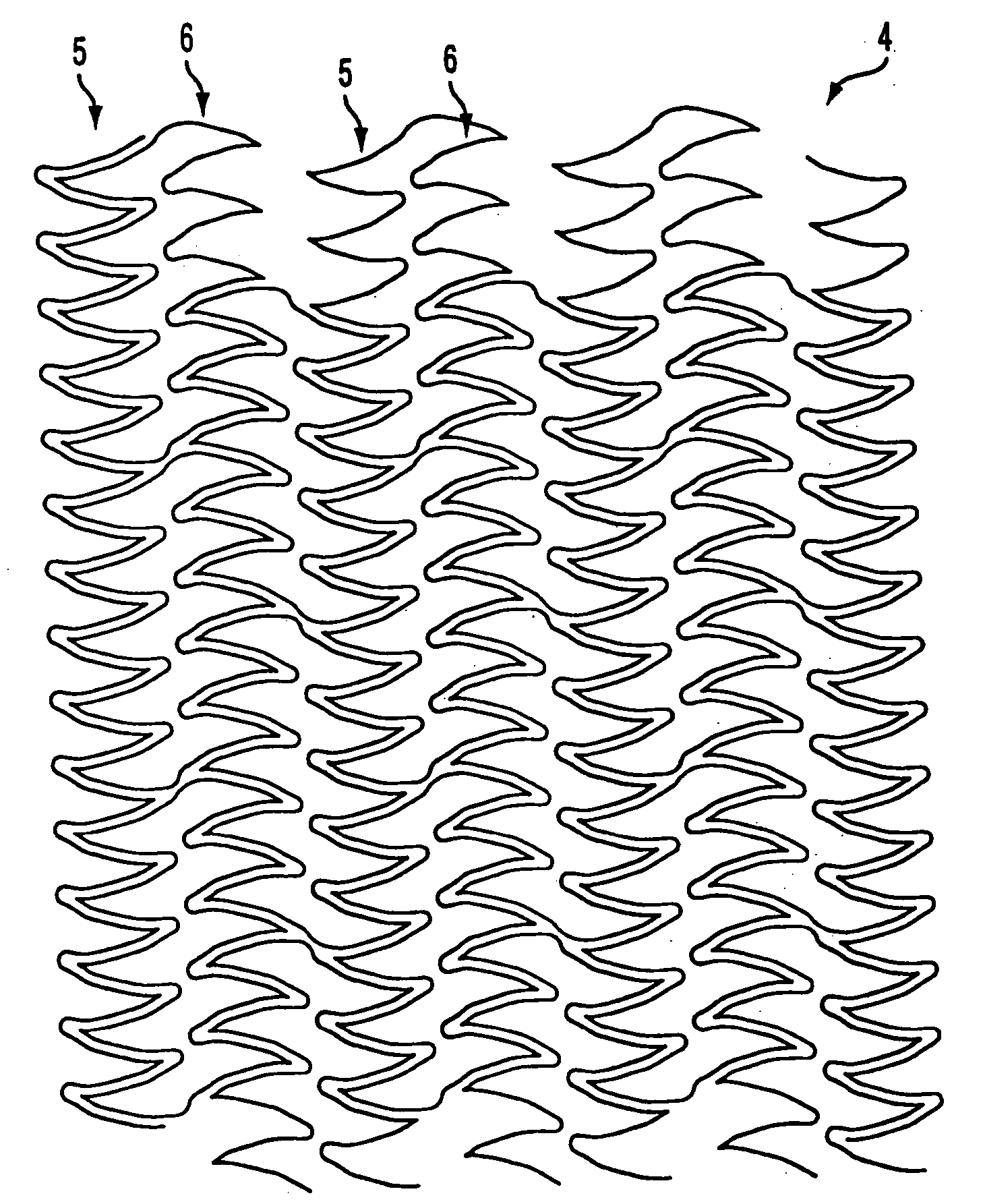
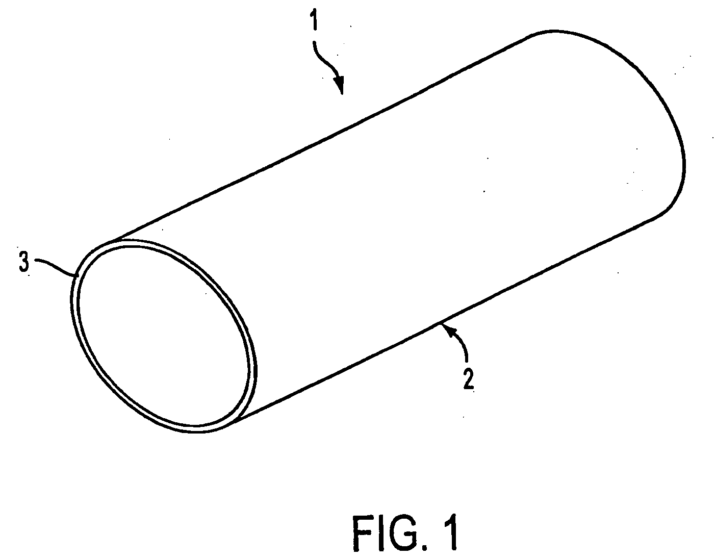
[0030] Referring to FIG. 1, stent 1 comprises tubular flexible body 2. Tubular flexible body 2, in turn, comprises wall 3 having a web structure, as described hereinbelow with respect to FIGS. 2-9. Stent 1 and its web structure are expandable from a contracted delivery configuration to an expanded deployed configuration. Depending on the material of fabrication, stent 1 may be either self-expanding or expandable using a balloon catheter. If self-expanding, the web structure is preferably fabricated from a superelastic material, such as a nickel-titanium alloy. Furthermore, stent 1 preferably is fabricated from biocompatible or biodegradable materials. It also may be radiopaque to facilitate delivery, and it may comprise an external coating C that retards thrombus formation or restenosis within a vessel. The coating alternatively may deliver therapeutic agents into the patient's blood stream.

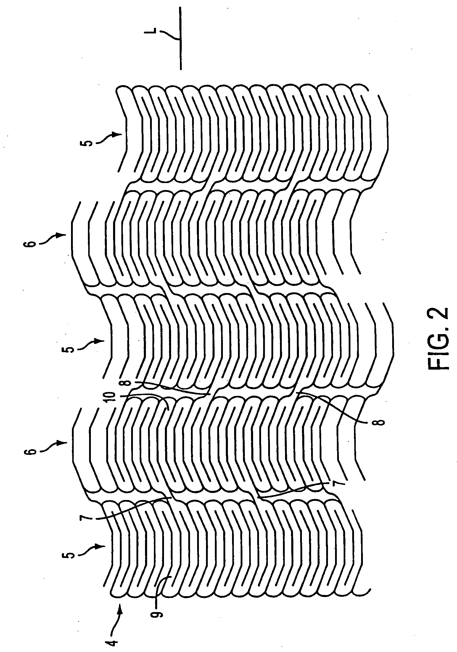
[0031] With reference to FIGS. 2-4, a first embodiment of the web structure of stent 1 is de...


PUM


Abstract

The present invention provides a stent comprising a tubular flexible body having a wall with a web structure that is expandable from a contracted delivery configuration to deployed configuration. The web structure comprises a plurality of neighboring web patterns, where each web patterns is composed of adjoining webs, and the web patterns are interconnected by connection elements. Each adjoining web comprises a central section interposed between two lateral sections to form concave or convex configurations.

Description

REFERENCE TO RELATED APPLICATIONS [0001] The present application is a continuation application of U.S. patent application Ser. No. 10 / 743,857, filed Dec. 23, 2003, which is a continuation application of U.S. patent application Ser. No. 09 / 742,144, filed Dec. 19, 2000, now U.S. Pat. No. 6,682,554, which is a continuation-in-part application of U.S. patent application Ser. No. 09 / 582,318, filed Jun. 23, 2000, now U.S. Pat. No. 6,602,285, which claims the benefit of the filing date of International Application PCT / EP99 / 06456, filed Sep. 2, 1999, which claims priority from German application 19840645.2, filed Sep. 5, 1998.FIELD OF THE INVENTION [0002] The present invention relates to stents. More particularly, the present invention relates to stents having a web structure configured to expand from a contracted delivery configuration to an expanded deployed configuration. BACKGROUND OF THE INVENTION [0003] Various stent designs are known in the art. These stents form vascular prostheses ...

Claims


Application Information

Patent Timeline
Patent Type & Authority Applications(United States)
IPC IPC(8): A61F2/06A61F2/90
CPCA61F2/91A61F2/915A61F2002/91558A61F2002/91533A61F2002/91508
Inventor VON OEPEN, RANDOLFSEIBOLD, GERD
Owner ABBOTT LAB VASCULAR ENTERPRISE
Why Eureka
Try Eureka