Travel safety system for vehicle

a safety system and vehicle technology, applied in the direction of pedestrian/occupant safety arrangement, using reradiation, instruments, etc., can solve the problems of driver discomfort or vexation, warning or automatic braking,

Inactive Publication Date: 2005-01-06
HONDA MOTOR CO LTD
View PDF23 Cites 48 Cited by
  • Summary
  • Abstract
  • Description
  • Claims
  • Application Information

AI Technical Summary

Benefits of technology

Accordingly, it is an object of the present invention to prevent a safety system from being unnecessarily actuated, when an overlap amount in a vehicle-width direction between a subject vehicle and a preceding vehicle is temporarily generated.
With the above-described arrangement, the operation of the safety system for avoiding the contact of the vehicle with the object existing in the travel direction of the vehicle is controlled based on the time for which the object existing in the travel direction of the vehicle exists in the predetermined region where there is the possibility of contact with the vehicle. Therefore, when it has been determined that there is temporarily the possibility of contact with the object due to the course change of the vehicle or the movement of the object, it is possible to prevent the safety system from being unnecessarily actuated to provide a sense of discomfort to the driver.
With the above-described arrangement, the predetermined period for operating the safety system is set such that the predetermined period for the operation of the primary warning means when the possibility of contact is relatively low is longer than that for the operation of the secondary warning means when the possibility of contact is relatively high. Therefore, it is possible to prevent the primary warning means from being frequently actuated to give the driver vexation, and to immediately actuate the secondary warning means when an object break into a space just in front of the subject vehicle, thereby providing an enhancement in safety.
With the above-described arrangement, the predetermined period for operating the safety system is set such that the predetermined period for the operation of the secondary decelerating means when the possibility of contact is relatively high, is longer than that for the operation of the primary decelerating means when the possibility of contact is relatively low. Therefore, it is possible to prevent an excessive actuation of the secondary decelerating means which generates a stronger decelerating force, thereby providing an enhancement in reliability.
With the above-described arrangement, the predetermined period for operating the safety system is set such that the predetermined period for the operation of the secondary steering means when the possibility of contact is relatively high, is longer than that for the operation of the primary steering means when the possibility of contact is relatively low. Therefore, it is possible to prevent an excessive actuation of the secondary steering means which generates a stronger steering torque, thereby providing an enhancement in reliability.

Problems solved by technology

However, in the conventional travel safety system, in such a case where the subject vehicle or a preceding vehicle has changed its course to traverse a traffic lane, if the preceding vehicle temporarily traverses the course of the subject vehicle to generate a overlap amount in a vehicle-width direction, it is determined that there is a possibility that the subject vehicle comes into contact with the preceding vehicle, leading to a possibility that the warning or the automatic braking is carried out.
If the overlap amount is generated just for a moment in this way, then the warning or the automatic braking is carried out although the possibility of contact is actually law, resulting in a problem that a driver feels a sense of discomfort or vexation.

Method used


Image

  • Travel safety system for vehicle
  • Travel safety system for vehicle
  • Travel safety system for vehicle

Examples


Embodiment Construction

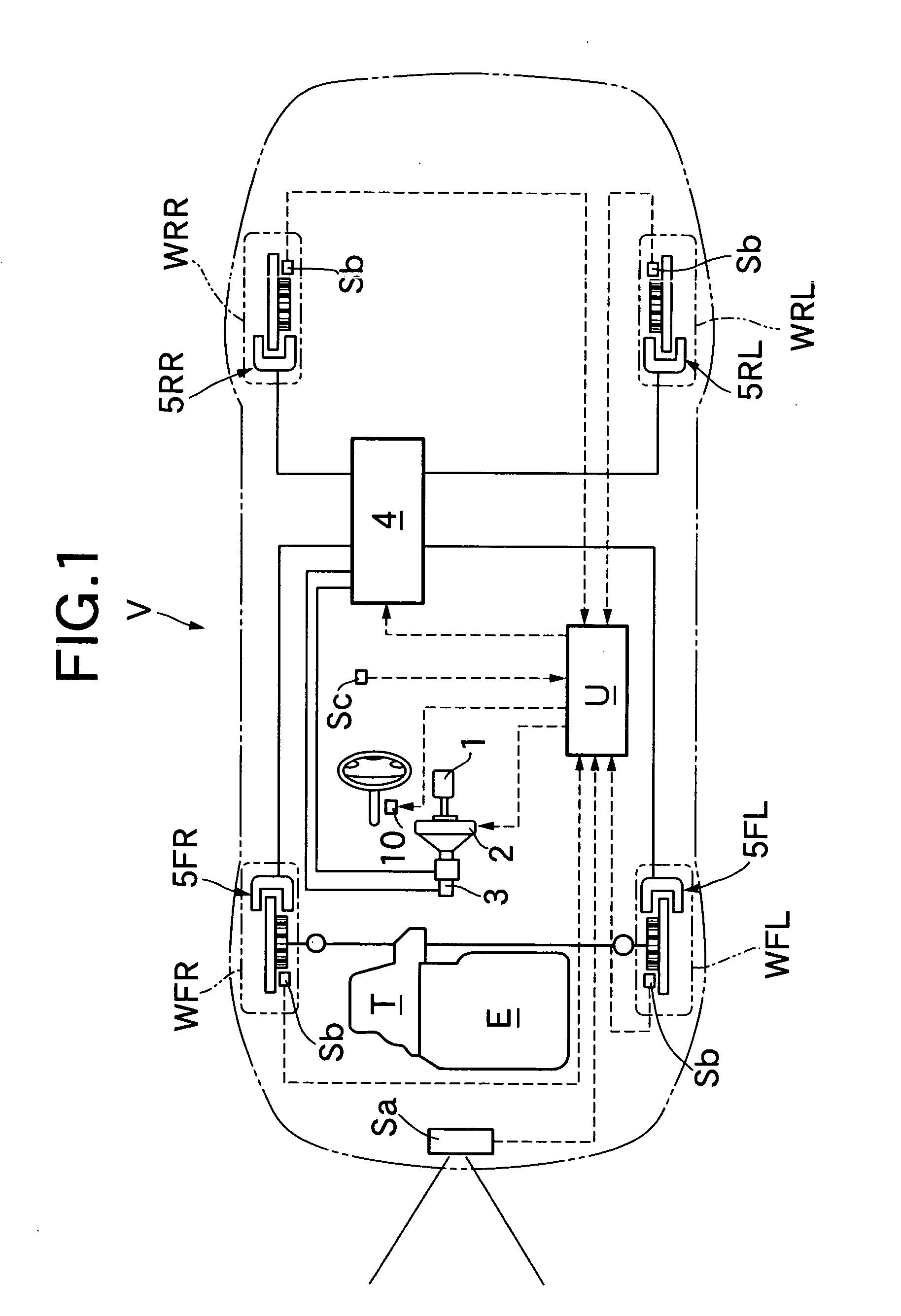
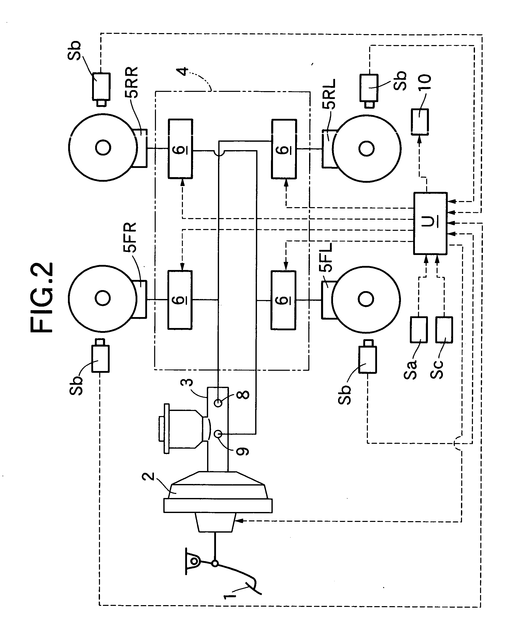
An embodiment of the present invention will now be described with reference to FIGS. 1 to 5.

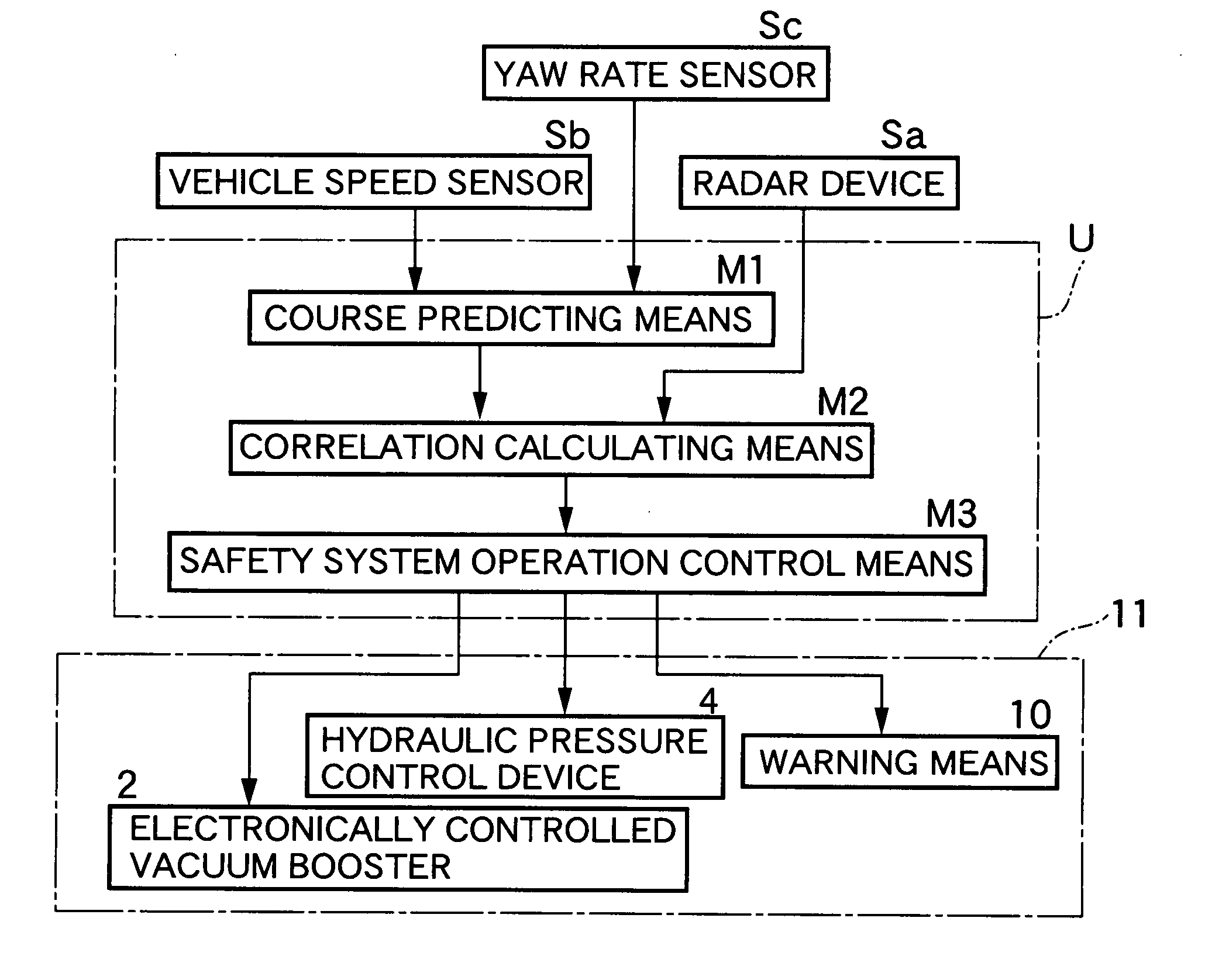
As shown in FIGS. 1 and 2; a four-wheel vehicle (subject vehicle) V provided with a travel safety system according to the present embodiment includes left and right front wheels WFL and WFR as driven wheels to which a driving force of an engine E is transmitted through a transmission T, and left and right rear wheels WRL and WRR as follower wheels which are rotated with the traveling of the vehicle V. A brake pedal 1 operated by a driver is connected to a master cylinder 3 through an electronically controlled vacuum booster 2. The electronically controlled vacuum booster 2 is adapted to mechanically boost a depression force on the brake pedal 1 to actuate the master cylinder 3, and to actuate the master cylinder 3 by a braking command signal from an electronic control unit U during automatic braking without the operation of the brake pedal 1. When the depression force is applied to the bra...


PUM


Abstract

In a travel safety system for a vehicle: a preceding vehicle V1 in a travel direction of a subject vehicle V is detected by a radar device; an overlap amount δ (smaller one of δ(L) and δ(R)), at which the preceding vehicle V1 overlaps a predicted course for the subject vehicle V, is calculated; and when time for which the over lap amount δ exceeding a predetermined value exceeds a predetermined period, it is determined that there is a possibility that the subject vehicle V comes into contact with the preceding vehicle V1, and a safety system comprising a warning or an automatic braking is actuated. Thus, if it is determined that there is a possibility of contact between the subject vehicle V and the preceding vehicle V1 due to course change of the subject vehicle V or the preceding vehicle, it is possible to prevent the safety system from being unnecessarily actuated to provide a sense of discomfort to a driver.

Description

BACKGROUND OF THE INVENTION 1. Field of the Invention The present invention relates to a travel safety system for a vehicle, which is designed so that an object is detected by an object detecting means mounted on the vehicle, and when there is a possibility that the vehicle comes into contact with the object, the safety system is actuated to avoid the contact. 2. Description of the Related Art Japanese Patent Application Laid-open No. 11-23705 discloses a conventional travel safety system, in which an object existing in a travel direction of a subject vehicle is detected by a radar device, the presence or absence of a possibility of contact between the subject vehicle and the object is determined based on an overlap amount (an avoiding steerage amount) in a vehicle-width direction, and when it is determined that there is the possibility of contact, a warning or an automatic braking is carried out to avoid the contact of the subject vehicle with the object. However, in the conve...

Claims


Application Information

Patent Timeline
Patent Type & Authority Applications(United States)
IPC IPC(8): B60R21/00G01S17/931B60K31/00B60T7/12G01S13/931G08G1/16
CPCG01S13/931G01S17/936Y02T10/84G01S2013/9353G01S2013/9342G01S2013/9346G01S2013/9325G01S2013/93185G01S2013/9318G01S2013/932G01S17/931
Inventor URAI, YOSHIHIROOTABE, MAKOTOKODAKA, KENJI
Owner HONDA MOTOR CO LTD
Why Eureka
Try Eureka