
Solar lighting arrangement for outdoor umbrella

a solar energy and umbrella technology, applied in the field of outdoor umbrellas, can solve the problems of not being able to guarantee the power of external power sources, not being able to shelter disadvantages, and not being able to guarantee external power sources, at least in the sense of electrical power sources, so as to achieve economic effects of operation

Active Publication Date: 2005-01-13
MA
View PDF11 Cites 9 Cited by
  • Summary
  • Abstract
  • Description
  • Claims
  • Application Information

AI Technical Summary

Benefits of technology

[0010] A main object of the present invention is to provide an outdoors umbrella which incorporates with a solar lighting arrangement for providing illumination utilizing solar energy as an external energy source. Thus, the solar lighting arrangement is environmentally friendly and economical to operate.
[0011] Another object of the present invention is to provide an outdoors umbrella with a solar lighting arrangement, wherein the electrical operation of the solar light system is substantially unaffected by the folding and unfolding operation of the outdoors umbrella so that it is capable of fully operating while the outdoors umbrella is partially or inclinedly erected.
[0012] Another object of the present invention is to provide an outdoors umbrella with a solar lighting arrangement which does not alter the original structural design of the outdoors umbrella, so as to minimize any potential risk of damage to the solar lighting arrangement while the outdoor umbrella is folding or unfolding.
[0014] Another object of the present invention is to provide an outdoors umbrella comprising a solar lighting arrangement, wherein no complicated mechanical and electrical structure and mechanism is required to incorporate with the outdoors umbrella so as to minimize the manufacturing and related cost of the present invention.
[0021] a plurality of illuminating units each comprising an illuminator electrically connected to the solar energy collector through the awning frame and a coupling joint connecting the illuminator to the respective supporting arm in a movably suspended manner such that by selectively adjusting a position of the light support along the supporting shaft, the illuminators are suspendedly self-repositioned for maximizing a light coverage area within the shadowing area;

Problems solved by technology

The very advantage and convenience of the typical outdoors umbrella, however, do not shelter its disadvantages.
Yet in an outdoors environment, the external power source, at least in the sense of the most typical power source for lighting system—electrical power source, cannot be guaranteed.
One might utilize a rechargeable battery as the power source, but an additional step of charging the battery is inevitably needed.
Very often, charging the battery can only be taken place when the umbrella is idle.
Therefore, for example, when the user of the umbrella forgets charging the battery, the lighting system would not work on the next day.
Sometimes, where the rechargeable battery cannot be conveniently detached from the outdoors umbrella, charging the battery would mean allocating extra space to store or to place the outdoor umbrella while the battery is being recharged.
The mounting arrangement of most of the outdoors umbrellas represents another problem.
A considerable numbers of outdoors umbrellas have their lighting system mounted insecurely or in such a manner that the lighting system is functionally incompatible with the normal operation of the outdoor umbrellas themselves.
As result, the performance of the respective lighting system is far from satisfactory.
For example, during folding and unfolding operations of the outdoors umbrella, the awning ribs thereof may accidentally destroy the illuminating units of the lighting system.
If the lighting system is so insecure that, when subject to certain outdoors phenomenon, such as against a sudden strong wind, the lighting system is incapable of safely or unstably operating, it would not only cause disruption to the activities in which it uses, but also harm to the users, especially those standing or sitting within the lighting zone.
As a result, where the outdoors umbrella needs to be inclinedly supported on the ground in order to shield a particular direction, or partially opened for a particular purpose, the lighting system could not be satisfactorily operated.

Method used


Image

  • Solar lighting arrangement for outdoor umbrella
  • Solar lighting arrangement for outdoor umbrella
  • Solar lighting arrangement for outdoor umbrella

Examples


Embodiment Construction

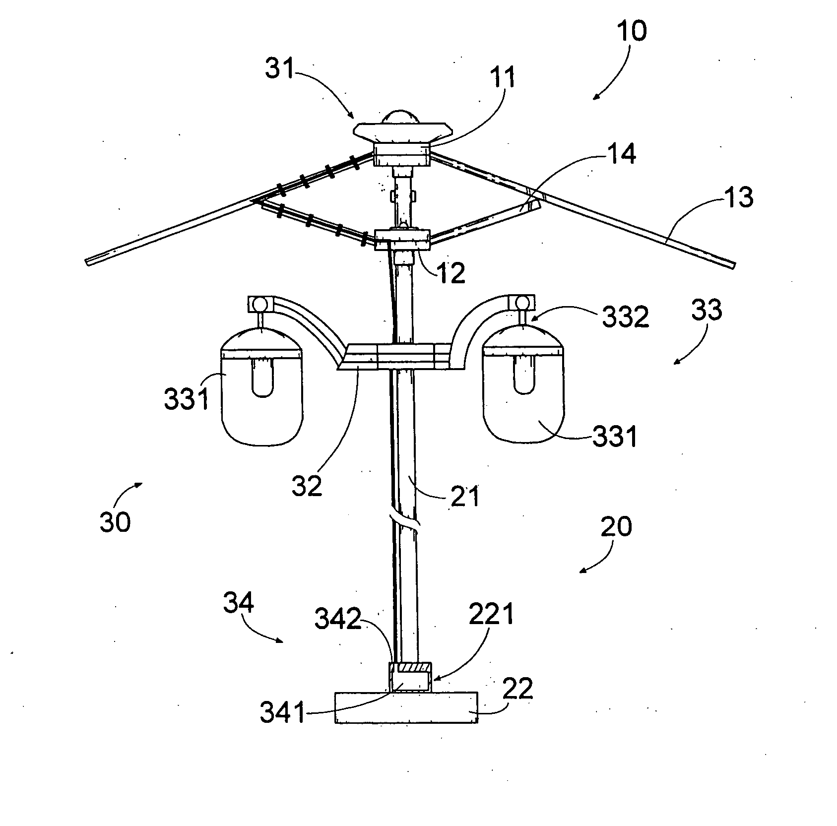
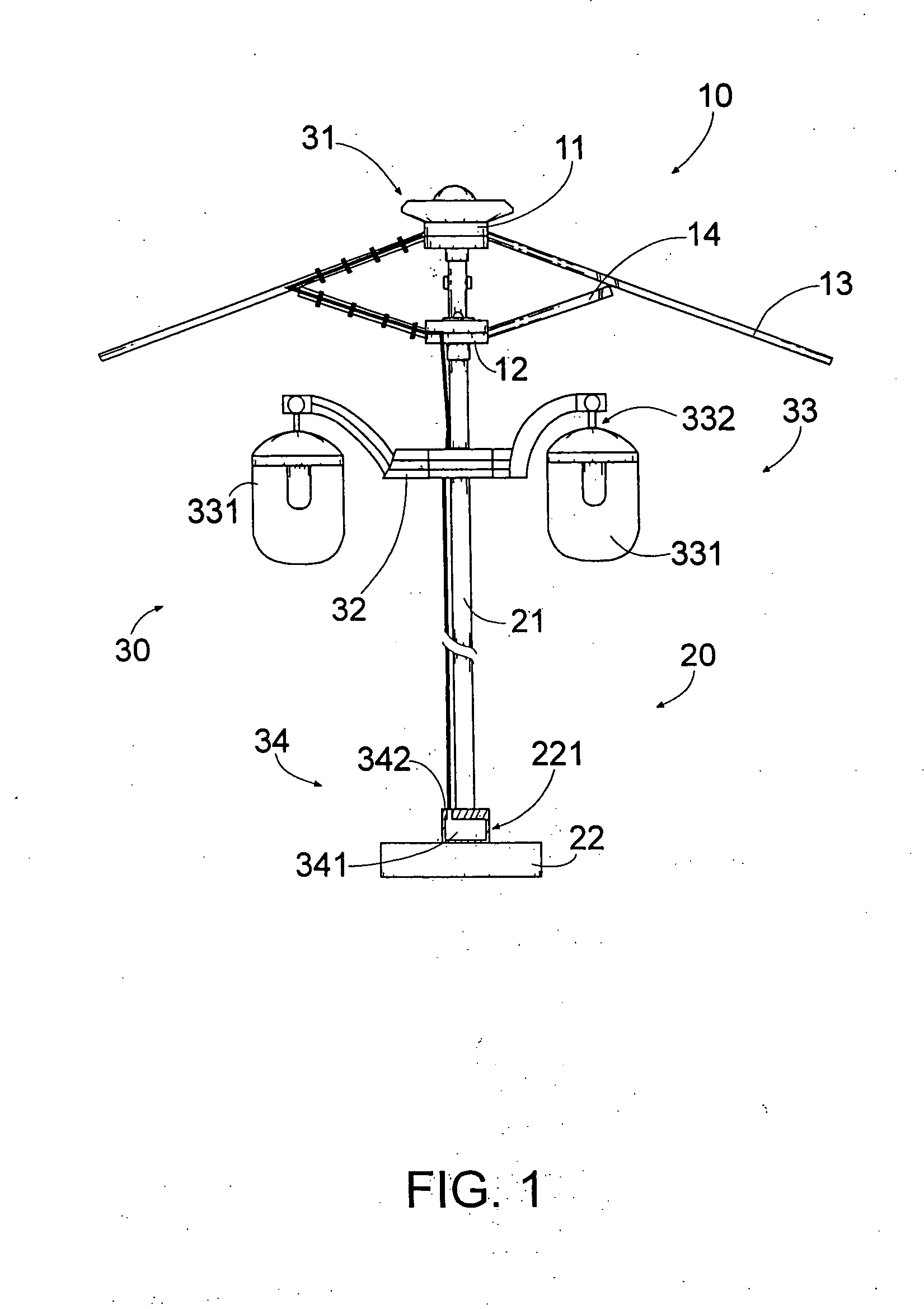
[0037] Referring to FIG. 1 of the drawings, an outdoor umbrella 1 according to a preferred embodiment of the present invention is illustrated, wherein the outdoor umbrella 1, such as a conventional outdoor umbrella, comprises an awning frame 10 defining a shadowing area 101 thereunder and a supporting frame 20 comprising a supporting shaft 21 having an upper portion connected to the awning frame 10.

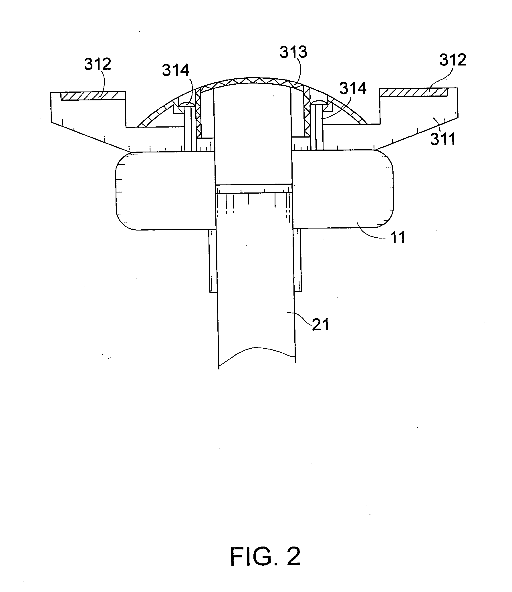
[0038] The outdoor umbrella 1 further comprises a solar lighting arrangement 30 comprising a solar energy collector 31 mounted on top of the awning frame 10 for collecting solar energy, a light support 32, and a plurality of illuminating units 33.

[0039] The light support 32, which is adjustably mounted along the supporting shaft 21 at a position within the shadowing area 101 of the awning frame 10, comprises a plurality of supporting arms 321 radially extended from the supporting shaft 21.

[0040] Each of illuminating units 33 comprises an illuminator 331 electrically connected to the so...


PUM


Abstract

A solar lighting arrangement, which is incorporated with an outdoors umbrella, includes a solar energy collector mounted on top of the outdoors umbrella, a chain lighting arrangement, an attachable lighting system, and a light support, which is adjustably mounted along a supporting shaft of the outdoors umbrella at a position within the shadowing area of the awning frame, including a plurality of supporting arms radially extended from the supporting shaft, and a plurality of illuminators connecting to the supporting arms respectively in a movably suspended manner such that by selectively adjusting a position of the light support along the supporting shaft, the illuminators are suspendedly self-repositioned for maximizing a light coverage area within the shadowing area.

Description

CROSS REFERENCE OF RELATED APPLICATION [0001] This is a Continuation-In-Part application of a non-provisional application having an application Ser. No. 10 / 436,192 and a filing date of May 12, 2003.BACKGROUND OF THE PRESENT INVENTION [0002] 1. Field of Invention [0003] The present invention relates to an outdoors umbrella, and more particularly to an outdoors umbrella incorporated with a solar lighting arrangement for securely providing illumination by utilizing solar energy. [0004] 2. Description of Related Arts [0005] Outdoors umbrellas have been proved to be extremely popular among those frequently expose to outdoor environment. In the daytime, a typical outdoor umbrella may be utilized as a temporary shelter so that people or instruments under the umbrella are protected from high temperature or vigorous sunlight. Moreover, depending on the material by which the umbrella fabric is fabricated, even in cloudy or rainy weather, the outdoors umbrella may be utilized as a rain shelter...

Claims


Application Information

Patent Timeline
Patent Type & Authority Applications(United States)
IPC IPC(8): A45B3/02A45B3/04A45B23/00A45B25/06A45B25/10E04B7/16F21SF21S9/03F21V21/30F21V21/34F21V33/00H02N6/00
CPCA45B3/04F21Y2113/02A45B25/10A45B2023/0012A45B2023/0037A45B2023/005A45B2200/1018A45B2200/1027F21S9/035F21V21/30F21V21/34F21V33/006F21W2131/10F21Y2101/02A45B25/06F21Y2113/20F21Y2115/10Y02B20/72
Inventor LI, WANDA YING
Owner MA
Learn More