Breather chamber structure for internal combustion engine and internal combustion engine

Inactive Publication Date: 2005-01-13
TOYOTA JIDOSHA KK
View PDF8 Cites 37 Cited by
  • Summary
  • Abstract
  • Description
  • Claims
  • Application Information

AI Technical Summary

Benefits of technology

[0008] An object of the present invention is to provide a breather chamber structure for internal combustion engine, which is capable of separating oil from blo

Problems solved by technology

As a result, oil mist and the like in the blow-by gas is carried to the valve hole by the high velocity blow-by gas, and oil mist stick to the circumference of the valve hole, a

Method used


Image

  • Breather chamber structure for internal combustion engine and internal combustion engine
  • Breather chamber structure for internal combustion engine and internal combustion engine
  • Breather chamber structure for internal combustion engine and internal combustion engine

Examples


Embodiment Construction

[0022] In the drawings, like numerals are used for like elements throughout.

[0023] A preferred embodiment of the present invention will be described below with reference to FIG. 1 through FIG. 7.

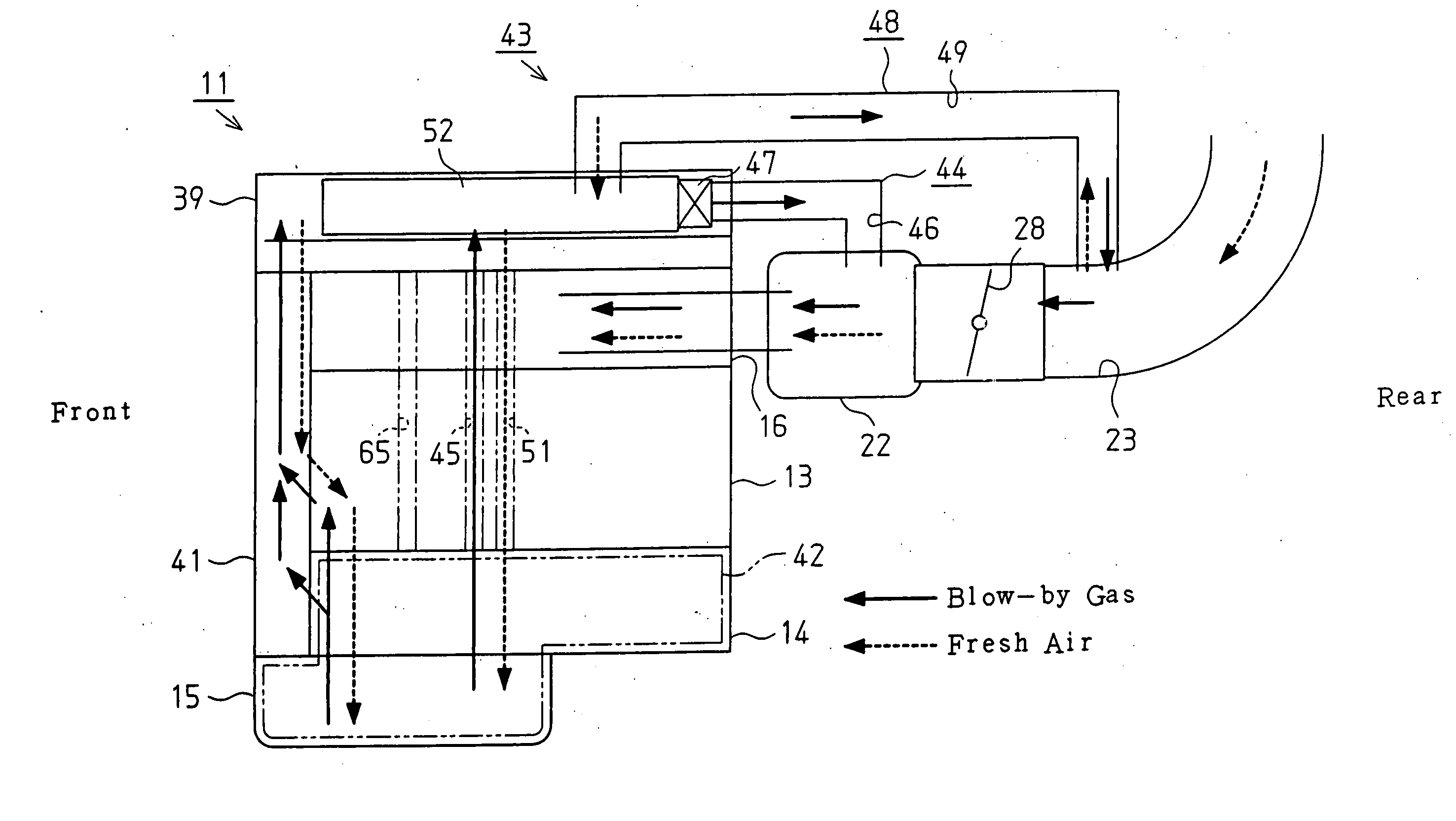
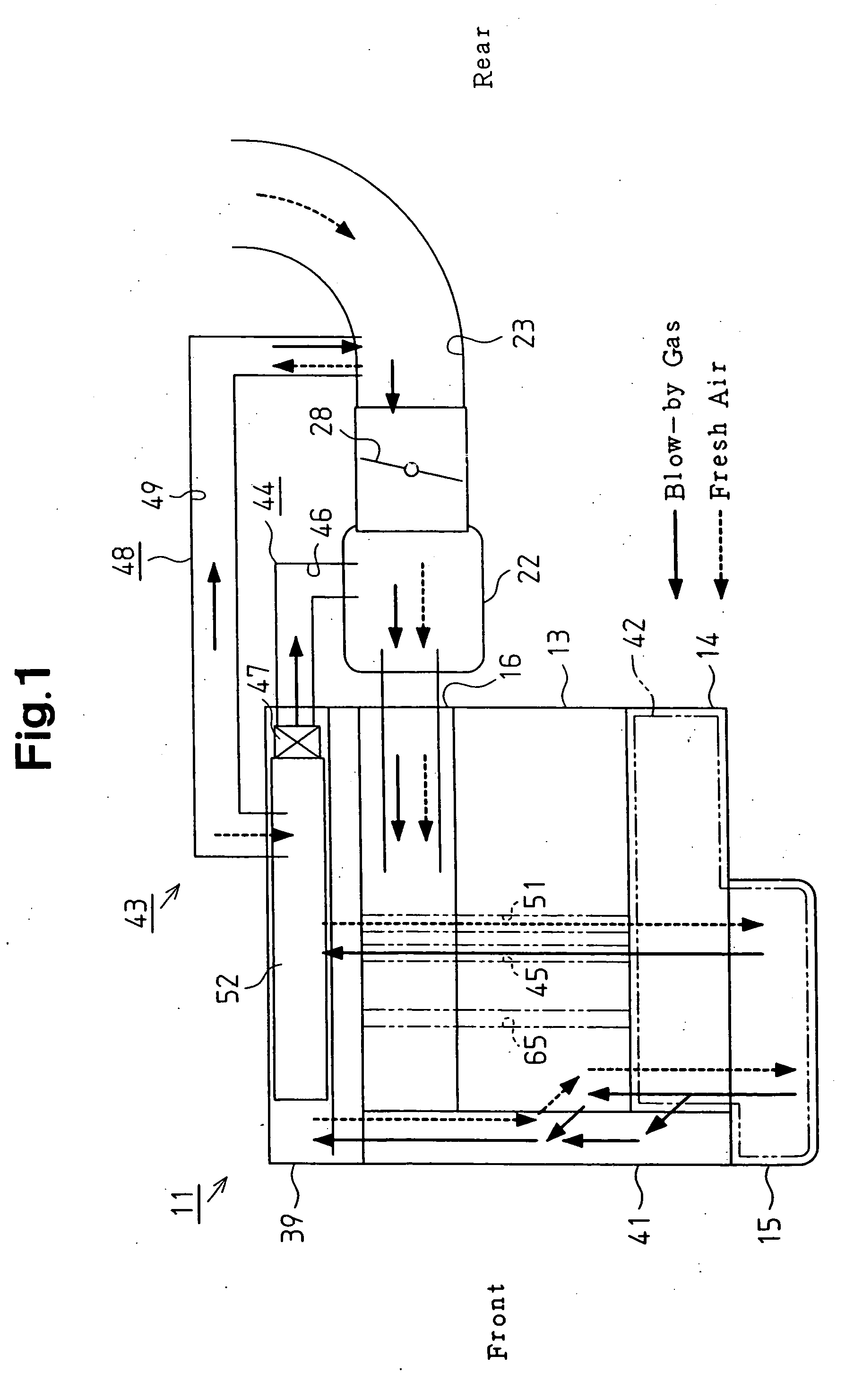
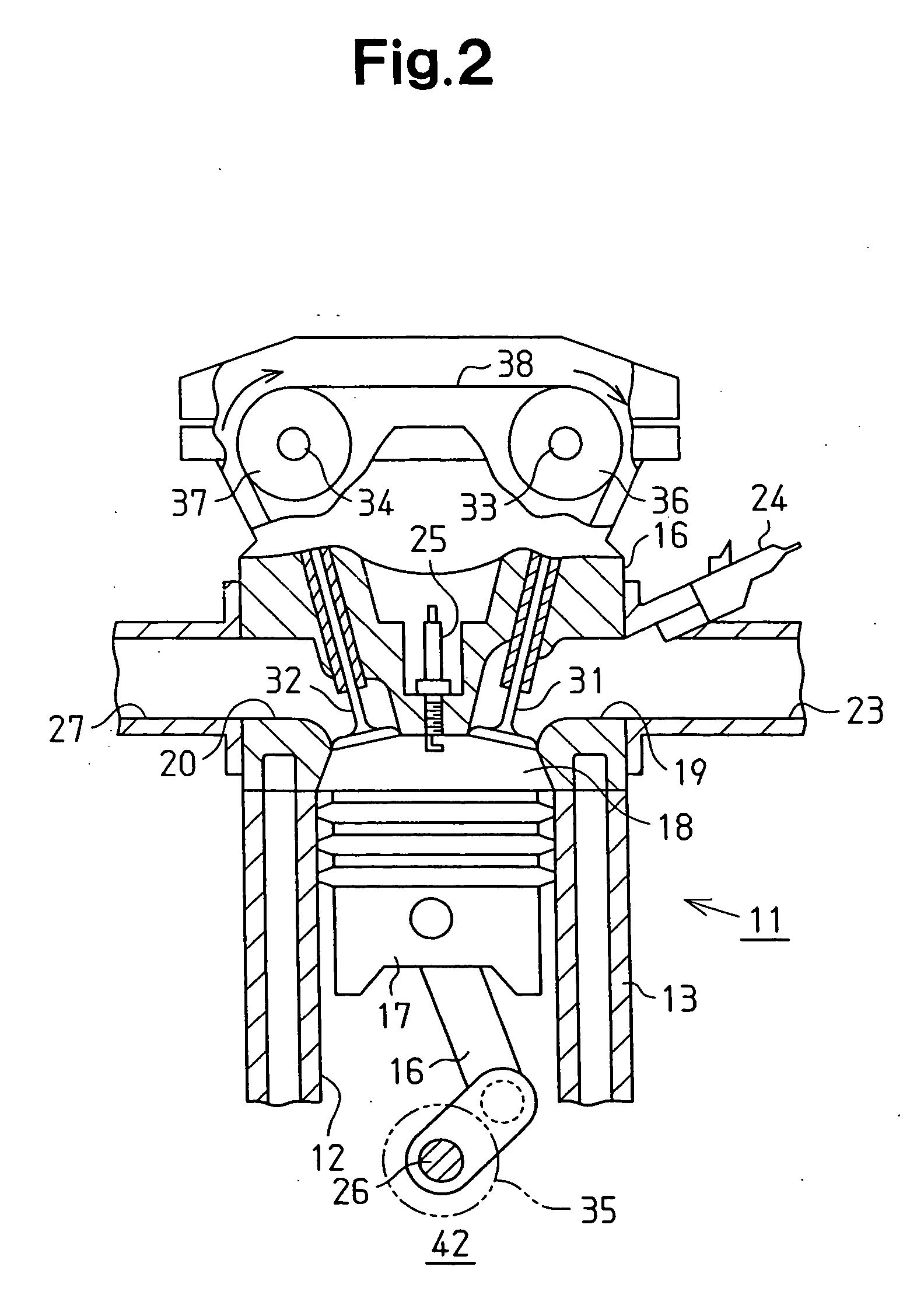
[0024] As shown in FIG. 1 and FIG. 2, a vehicle is equipped with a gasoline engine 11, which is an internal combustion engine. The engine 11 is provided with a cylinder block 13 having a plurality of cylinders 12. Underneath the cylinder block 13 are fitted a crankcase 14 and an oil pan 15, and above it is fitted a cylinder head 16.

[0025] In this engine 11, air is sucked into the combustion chambers 18 of the cylinders 12 through an intake passage 23 and intake ports 19, and fuel is fed by injection through fuel injection valves 24. When the resultant mixture of fuel and air is ignited by ignition plugs 25, the mixture is combusted to reciprocate pistons 17 and thereby to turn a crankshaft 26, which is the output shaft of the engine 11. Exhaust gas resulting from the combustion of the mix...


PUM


Abstract

A breather chamber is located in a blow-by gas passage to separate oil from blow-by gas. A partitioning member partitions the interior of the breather chamber into a plurality of spaces. The partitioning member is arranged such that the spaces extend along the flowing direction of the blow-by gas and that an adjacent pair of the spaces are connected at ends in the flowing direction. A separating member is provided in at least one of the spaces. The separating member obstructs the flow of the blow-by gas in the associated space, thereby separating oil from the blow-by gas. Therefore, oil is separated from the blow-by gas securely and is prevented from being brought out of the breather chamber.

Description

BACKGROUND OF THE INVENTION [0001] The present invention relates to the structure of a breather chamber for separating oil drips and oil mist from blow-by gas, which accompanies the operation of internal combustion engine. This invention also pertains to an internal combustion engine. [0002] In a reciprocating engine in which the reciprocating motions of pistons are converted by a crank mechanism into rotary motions, blow-by gas (unburnt gas mixture and combustion gas) leaks from combustion chambers through the gaps between the pistons and cylinders. For this reason, the blow-by gas is usually returned through the air intake line into the combustion chambers to be re-combusted. [0003] In order to prevent oil drips and oil mist contained in blow-by gas from riding on the flow of blow-by gas and being discharged, the engine is equipped with a mechanism for separating oil drips and oil mist from blow-by gas. One of such mechanisms is disclosed as a “breather device for engine” in the J...

Claims


Application Information

Patent Timeline
IPC IPC(8): F01M13/00F01M13/02F01M13/04F02M25/06F02M35/10
CPCF01M13/023F01M13/025F01M13/0416Y02T10/121F02M25/06F02M35/10222F01M2013/0433Y02T10/12
Inventor IKEDA, EIJIMURAYAMA, MASAONAKAYAMA, TAKUONAKAMURA, YUKISOMA, MASATO
Owner TOYOTA JIDOSHA KK
Why Eureka
Try Eureka