
Method of inserting z-axis reinforcing fibers into a composite laminate

a technology of z-axis fiber reinforcement and composite laminate, which is applied in the direction of wood layered products, chemistry apparatus and processes, ways, etc., can solve the problems of matrix material cracking or buckling, cost and labor, and methods have deficiencies

Inactive Publication Date: 2005-01-13
EBERT COMPOSITES
View PDF26 Cites 34 Cited by
  • Summary
  • Abstract
  • Description
  • Claims
  • Application Information

AI Technical Summary

Benefits of technology

[0016] After the PDP has been actuated upwardly to its upper most position, it is then retracted downwardly to its initial position and simultaneously, the movable hollow tube would travel downwardly through the hole created in the x-y axis material. While this is happening, the tip of the PDP would remain inserted into the bottom end of the movable hollow tube to insure a smooth entry of the hollow tube through the aperture in the x-y axis material created by the PDP. Each z-axis fiber deposition unit has a mechanism for preventing withdraw of z-axis fiber from the x-y axis material when the movable hollow tube is withdrawn upwardly. Once the movable hollow tube has been raised to its upper position, the top end of z-axis fiber that has been inserted into the x-y axis material is severed. This would complete a whole cycle. Simultaneously, across the width of the housing each of the other z-axis fiber deposition units would have completed their cycle. Next, the x-y axis material is stepped forwardly to provide a new position for the z-axis fibers to be deposited. Alternatively, the method could provide structure for stepping the housing rearwardly instead of stepping forwardly the x-y axis composite material.

Problems solved by technology

Because the matrix is weaker in strength than the fiber (in many cases by at least an order of magnitude), the failure mechanism of these composites when test loaded toward their ultimate strength is a cracking or buckling or separation of the matrix material.
All of these methods have deficiencies, drawbacks and are expensive and labor intensive.

Method used


Image

  • Method of inserting z-axis reinforcing fibers into a composite laminate
  • Method of inserting z-axis reinforcing fibers into a composite laminate
  • Method of inserting z-axis reinforcing fibers into a composite laminate

Examples


Embodiment Construction

[0031] The method of inserting z-axis reinforcing fibers into a composite laminate will now be described by referring to FIGS. 1-6 of the drawings.

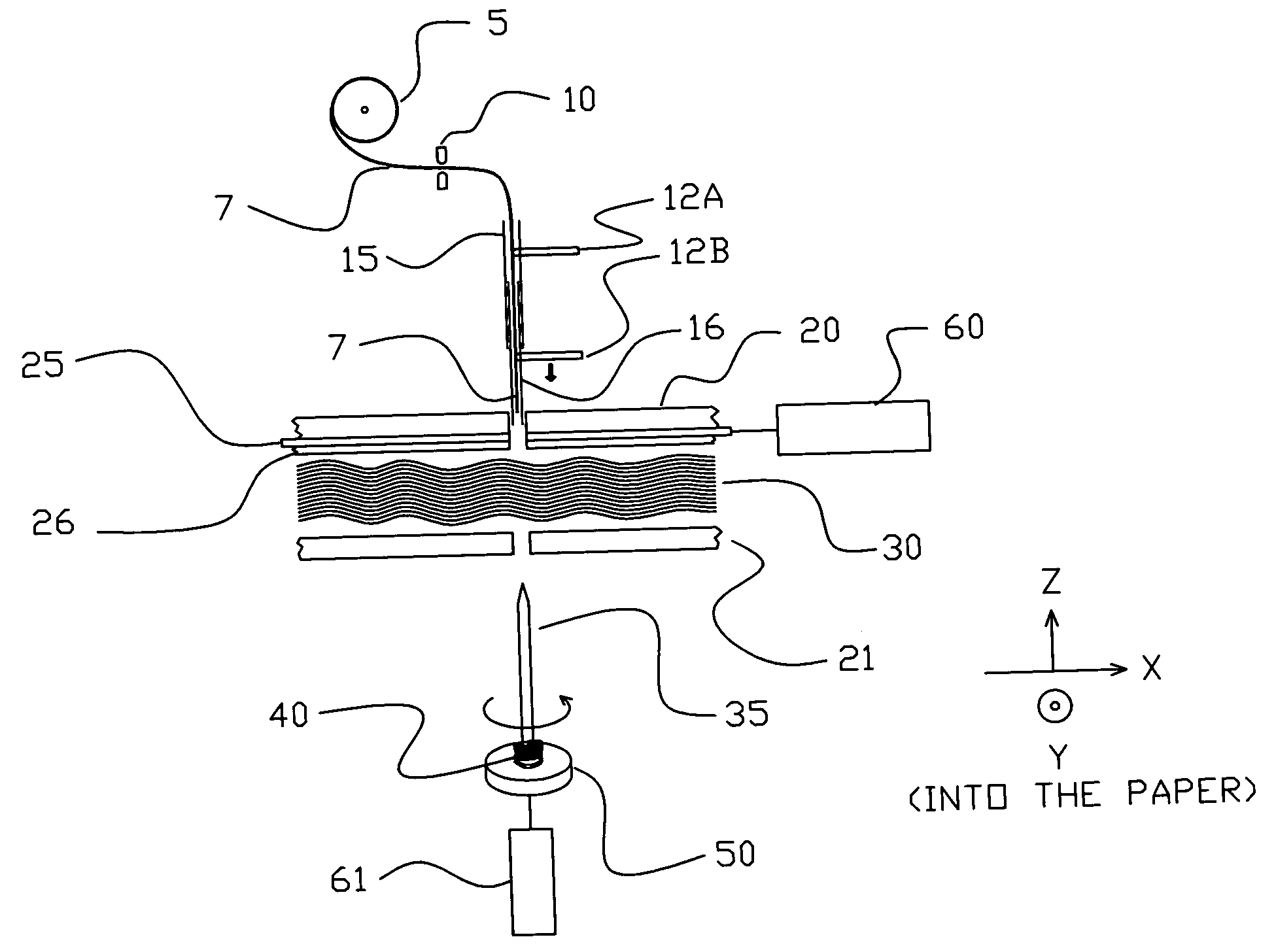
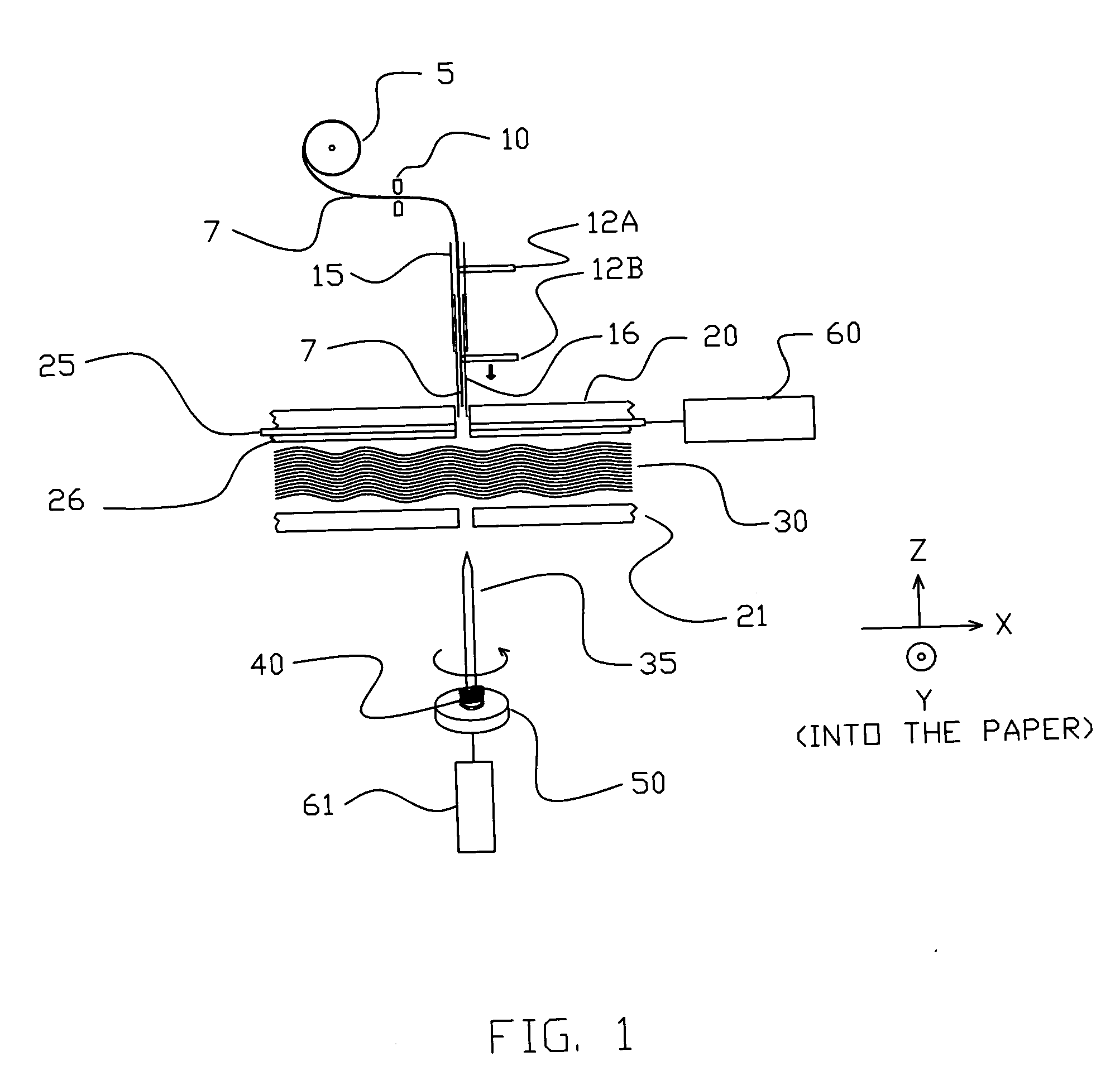
[0032]FIG. 1 shows a schematic elevation view of the novel z-axis fiber deposition process and the associated machinery. The key element of only one z-axis fiber deposition unit is illustrated in this figure. Following a description of FIG. 1, a more detailed, expanded description of multiple z-axis fiber deposition components will be discussed.

[0033] In FIG. 1, the cross section of a typical x-y axis material is identified by numeral 30. Material 30 is a continuously traveling laminate of x-y axis material. The direction of pultrusion and the continuous processing is defined as being in the x-axis direction and is left-to-right. The y-axis direction is into the paper. The z-axis direction is from top-to-bottom, through 3-D material 30. Only a few layers, or “plies” of x-y axis material 30 are shown, although clearly, additional layers ...


PUM

PropertyMeasurementUnit
Thicknessaaaaaaaaaa

Abstract

A method of inserting z-axis reinforcing fibers into a multi-layer composite laminate. Layers of material made up of z-axis fiber and y-axis fibers are automatically transported into a z-fiber deposition machine having a housing with upper and lower surfaces. Z-axis apertures are formed in the respective upper and lower surfaces. An elongated solid rod having a tapered front tip is aligned in close proximity to the aperture in the bottom surface. The rod is first rotated by a motor and then actuated upwardly completely through the thickness of the layer of x-y material by an actuator. A first hollow tube having a z-axis is axially aligned with the aperture in the top surface and a fiber bundle is threaded downwardly through a first hollow tube to a position adjacent its bottom end. The z-fiber deposition machine has structure to feed a predetermined length of the fiber bundle downwardly through the first hollow tube so that it follows the pathway in the x-y material formed by the rod which is now withdrawn downwardly through the aperture in the bottom wall. The z-axis fiber is thus deposited into the x-y material. The top end of the z-axis fiber is then severed and the x-y material is then advanced a predetermined distance to complete the cycle and is, thus, set to be repeated.

Description

CROSS-REFERENCE TO RELATED APPLICATIONS [0001] This patent application is a continuation-in-part application of U.S. patent application Ser. No. 09 / 922,053 filed Aug. 2, 2001, which issued as U.S. Pat. No. 6,645,333 on Nov. 11, 2003, and claims the priority of provisional patent application 60 / 281,838 filed Apr. 6, 2001 and provisional patent application 60 / 293,939 filed May 29, 2001.[0002] This invention was made with United States Government support under Cooperative Agreement 70NANB8H4059 awarded by NIST. The United States Government has certain rights in the invention.BACKGROUND OF THE INVENTION [0003] The invention relates to a method of producing a composite material and more specifically a process for incorporating z-axis fiber reinforcement into x-y axis composite material. [0004] Traditional composite materials are made up of resin matrix material and a quantity of 2-dimensional fibers, continuous in the x-y axis directions, but laminated in layers to produce a material thi...

Claims


Application Information

Patent Timeline
IPC IPC(8): B29C70/08B29C70/24B29C70/52B32B5/02B32B5/08E01C9/08E04C2/296
CPCB29C70/086E04C2/296B29C70/24B29C70/521B32B3/12B32B5/02B32B5/08B32B5/18B32B5/22B32B7/08B32B21/04B32B2250/03B32B2250/40B32B2262/0269B32B2262/101B32B2262/106E01C9/086B29C70/088B29C31/08B29K2105/04B32B5/24B32B2305/024
Inventor JOHNSON, DAVID W.GARRETT, SCOTT A.HOOK, JAMES M.MOYERS, STEPHEN G.
Owner EBERT COMPOSITES
Features
  • Generate Ideas
  • Intellectual Property
  • Life Sciences
  • Materials
  • Tech Scout
  • Unparalleled Data Quality
  • Higher Quality Content
  • 60% Fewer Hallucinations
Learn More