Multiple ball screw assembly with differing pitch used to optimize force and displacement of brake actuator

a technology of brake actuator and ball screw, which is applied in the direction of mechanically actuated brakes, actuators, brake types, etc., can solve the problems of large force needed to slow down a vehicle, add to the overall weight and cost of such a brake system, and large system weight and cost, so as to achieve fast and efficient application of braking force, reduce the effect of consuming large amounts of energy and reducing the cost of the system

Inactive Publication Date: 2005-01-13
ARVINMERITOR TECH
View PDF13 Cites 12 Cited by
  • Summary
  • Abstract
  • Description
  • Claims
  • Application Information

AI Technical Summary

Benefits of technology

[0006] The inventive electric motor brake assembly has a unique brake actuator that operates at two different speeds and two different forces to apply a brake pad to a rotor. The brake assembly moves the brake pad at a high speed and a low clamping force so that the brake pad may be placed in close proximity to the rotor quickly and without consuming large amounts of energy. Once the brake pad engages the rotor, the brake assembly then applies the brake pad at a lower speed and higher clamping force to permit the stronger braking forces to be applied when needed. In this way, the brake assembly quickly and efficiently applies braking forces for an electric braking system to slow a vehicle.

Problems solved by technology

The cylinder itself requires lines, connectors and other components that significantly add to the overall weight and cost of such a brake system.
While such a system can apply strong braking forces quickly to the rotor, the system is heavy and expensive to produce.
However, the forces necessary to slow a vehicle are large, particularly for commercial vehicles.
High torque output electric motors are expensive and consume a large amount of electricity from the vehicle's electrical system.
Moreover, while high torque electric motors provide sufficient braking force, they are generally slow turning motors.
A slow turning motor may cause an undesirable delay in brake actuation.

Method used


Image

  • Multiple ball screw assembly with differing pitch used to optimize force and displacement of brake actuator
  • Multiple ball screw assembly with differing pitch used to optimize force and displacement of brake actuator
  • Multiple ball screw assembly with differing pitch used to optimize force and displacement of brake actuator

Examples


Embodiment Construction

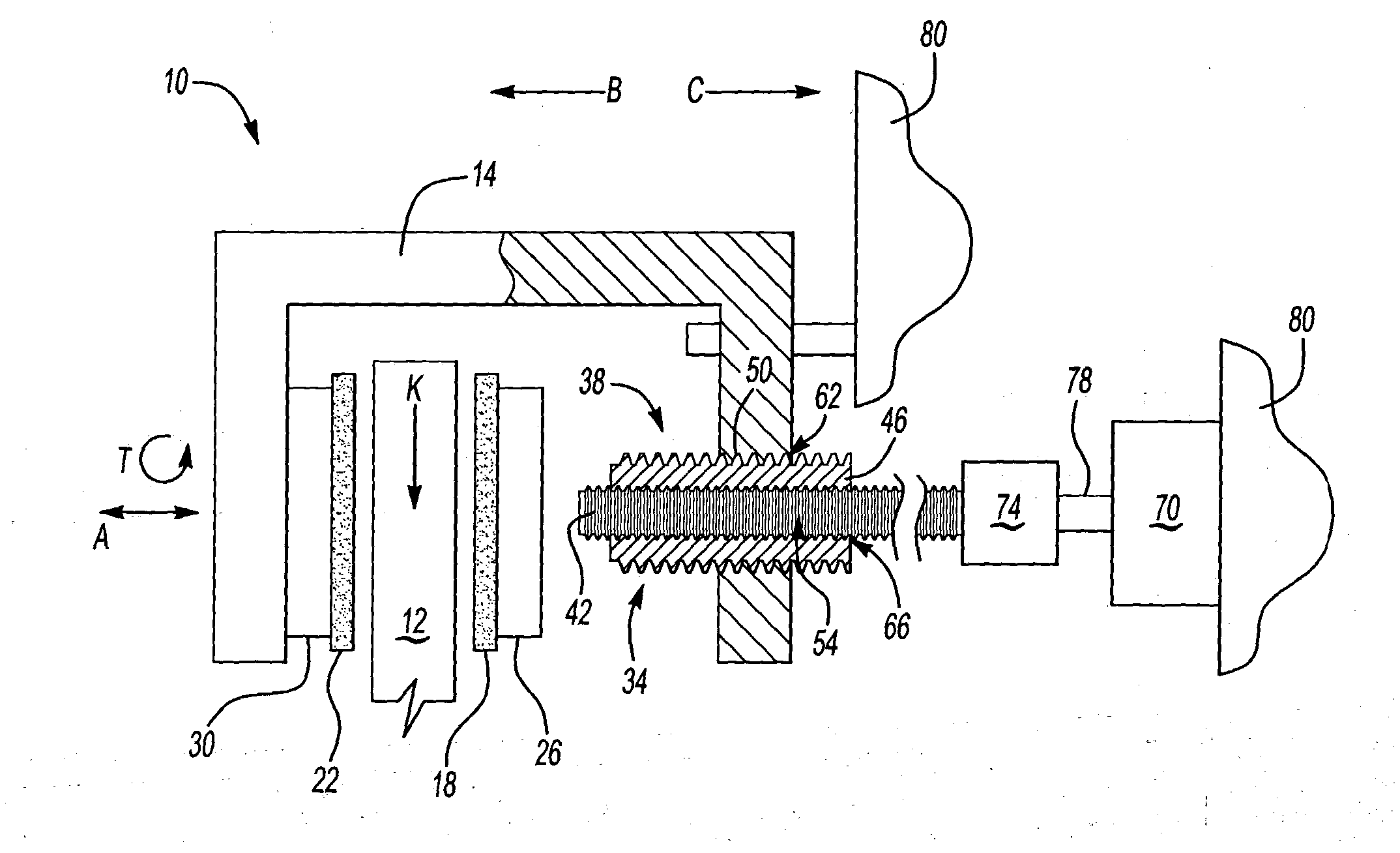
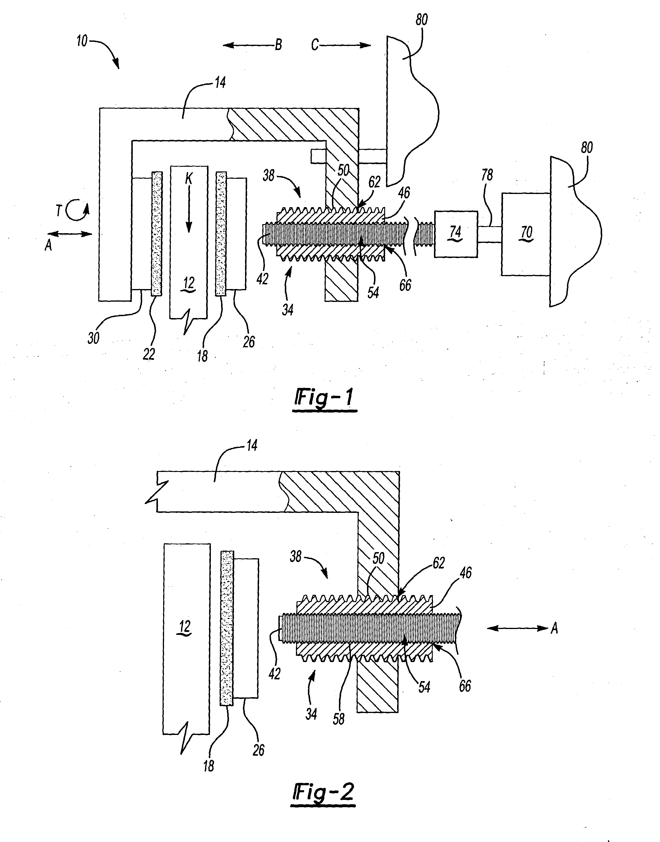
[0017]FIG. 1 illustrates a side view of inventive brake assembly 10 mounted to vehicle body 80. Brake assembly 10 comprises caliper 14 supported to vehicle body 80. Caliper 14 may be a sliding caliper, as is known in the art. Caliper 14 has spaced apart first 18 and second 22 brake pads. First brake pad 18 and second brake pad 22 are each mounted on first and second backing plates 26, 30 respectively. Second brake pad 22 and second backing plate 30 are fixed and mounted to caliper 14. First brake pad 18 and first backing plate 26 are supported, as known, to move relative to caliper 14. These particular features of brake assembly 10 are well known in the art. One of ordinary skill in the art will appreciate that this invention may be used with other brake configurations.

[0018] In contrast to conventional braking systems, brake assembly 10 is operatively connected to electric motor 70, which itself is mounted to caliper 50. Electric motor 70 provides the necessary braking forces to a...


PUM


Abstract

A brake assembly has a caliper with a first brake pad and a second brake pad. The first brake pad is moveable relative to the caliper. A brake actuator moves the first brake pad and has a first threaded member and a second threaded member. The first threaded member has first thread characteristics for moving the brake actuator at a first speed and a first force. The second threaded member has a second thread characteristics for moving the brake actuator at a second speed and a second force. The first speed is greater than the second speed while the first force is lower than the second force.

Description

BACKGROUND OF THE INVENTION [0001] This invention relates to a brake assembly for a motor vehicle. [0002] One type of brake system for a vehicle has a rotor that rotates with a wheel of the vehicle. To brake the vehicle, brake pads are applied to each side of the rotor, thereby creating friction to slow movement of the rotor. The brake pads are moved into contact with the rotor by a brake actuator driven by a heavy hydraulic or pneumatic cylinder. The cylinder itself requires lines, connectors and other components that significantly add to the overall weight and cost of such a brake system. While such a system can apply strong braking forces quickly to the rotor, the system is heavy and expensive to produce. [0003] Recently, manufacturers have sought to develop electrical braking systems that brake the vehicle through electrical motors linked to the brake pads. Such systems eliminate the need for the hydraulic or pneumatic cylinder, lines, connectors and related components of tradit...

Claims


Application Information

Patent Timeline
Patent Type & Authority Applications(United States)
IPC IPC(8): F16D55/08F16D65/14F16D65/18
CPCF16D65/18F16D2127/007F16D2125/405F16D2121/24
Inventor KRAMER, DENNIS A.JELLEY, FREDERICK A.KAY, JOSEPH A.BRICHTA, JAMES R.O'REILLY, DENNIS G.KEENEY, CHRISTOPHER S.KWAK, JAEHO
Owner ARVINMERITOR TECH
Why Eureka
Try Eureka