Seat cushion pumping device for vehicle

a technology for vehicle seats and pumping devices, which is applied in the direction of moving seats, gearing details, transportation and packaging, etc., can solve the problems of deterioration of braking force, incomplete clutching operation, and increase in wear of constituent parts, so as to facilitate clutching operation and enhance braking force. , the effect of easy adjustmen

Inactive Publication Date: 2005-01-13
DAS CO LTD
View PDF7 Cites 43 Cited by
  • Summary
  • Abstract
  • Description
  • Claims
  • Application Information

AI Technical Summary

Benefits of technology

[0017] Therefore, the present invention has been made in view of the above problems, and it is an object of the present invention to provide a seat cushion pumping device for a vehicle, which enables an overall height of a seat cushion to be easily adjusted by using a single pumping device, ensures a more easy clutching operation even with a relatively low operating force, and enhances a braking force, resulting in an improvement in durability, quality, and operation capability of the pumping device itself and the convenience of use thereof.

Problems solved by technology

The conventional seat cushion pumping device 100 suffers from defects in that, in operation, the clutch unit comes into frictional contact with an inner circumferential surface of a drum included in the base by means of the clutch blocks operated by the lever block, and frictional surfaces there between are concentrated on the same line, resulting in an incomplete clutching operation.
An additional defect of the conventional seat cushion pumping device consists in that, in relation to the lever block adapted to operate the clutch blocks, its relatively short radius from a center point to an outer circumferential surface thereof tends to generate an excessive load in operation, resulting in an increase in wear of constituent components.
Yet another defect of the conventional seat cushion pumping device consists in that, in relation to the brake unit, although the operating plate and brake pins are arranged equiangularly in three directions thus exhibiting visual stability, they cannot sufficiently resist the overall region of the body during an actual braking operation, resulting in a deterioration in a braking force due to a stress concentration phenomenon, thus causing a deterioration in durability, quality, and operation capability of the pumping device itself.

Method used


Image

  • Seat cushion pumping device for vehicle
  • Seat cushion pumping device for vehicle
  • Seat cushion pumping device for vehicle

Examples


Embodiment Construction

[0032] Reference will now be made in greater detail to a preferred embodiment of the invention, an example of which is illustrated in the accompanying drawings. Wherever possible, the same reference numerals will be used throughout the drawings and the description to refer to the same or like parts.

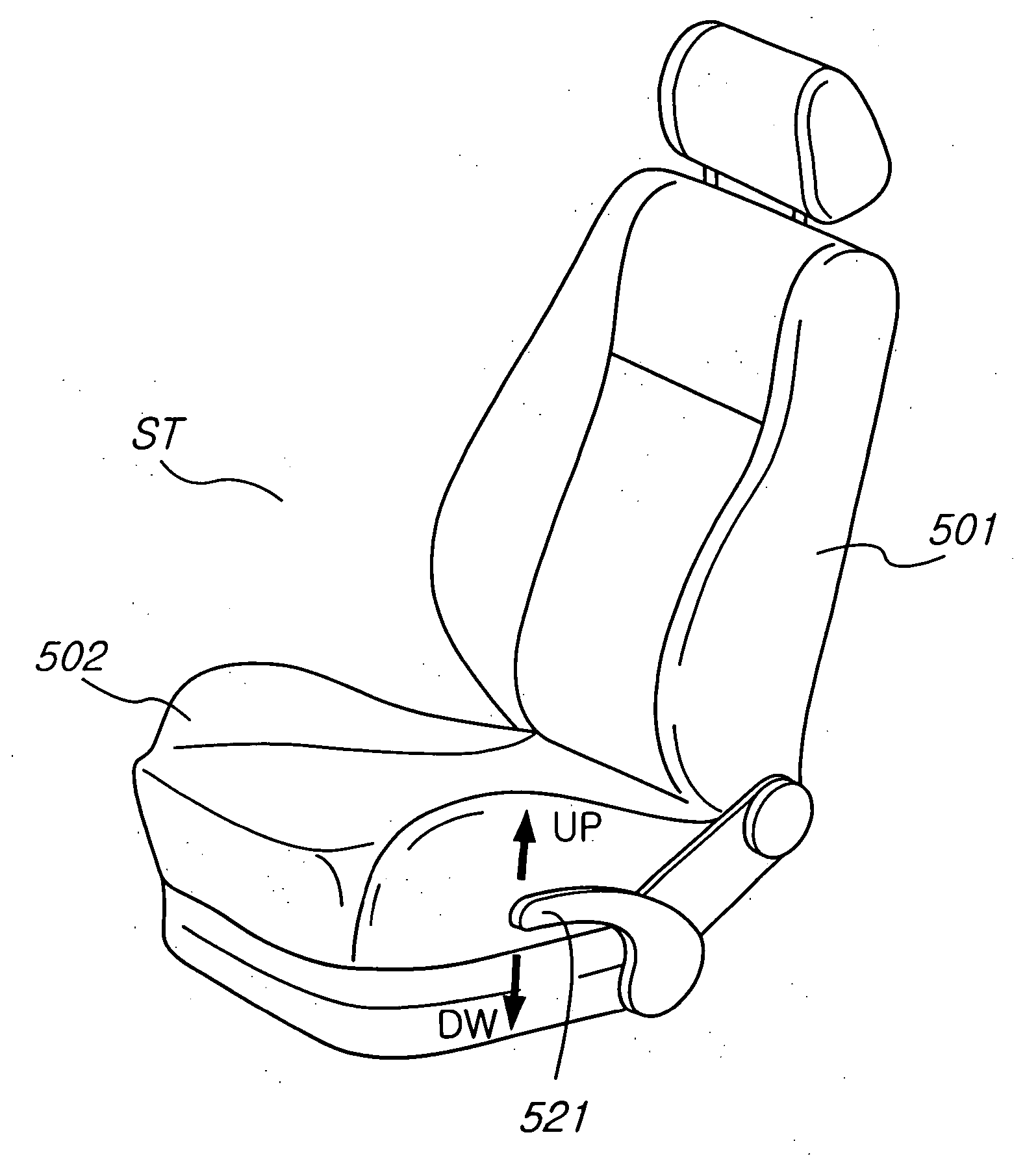
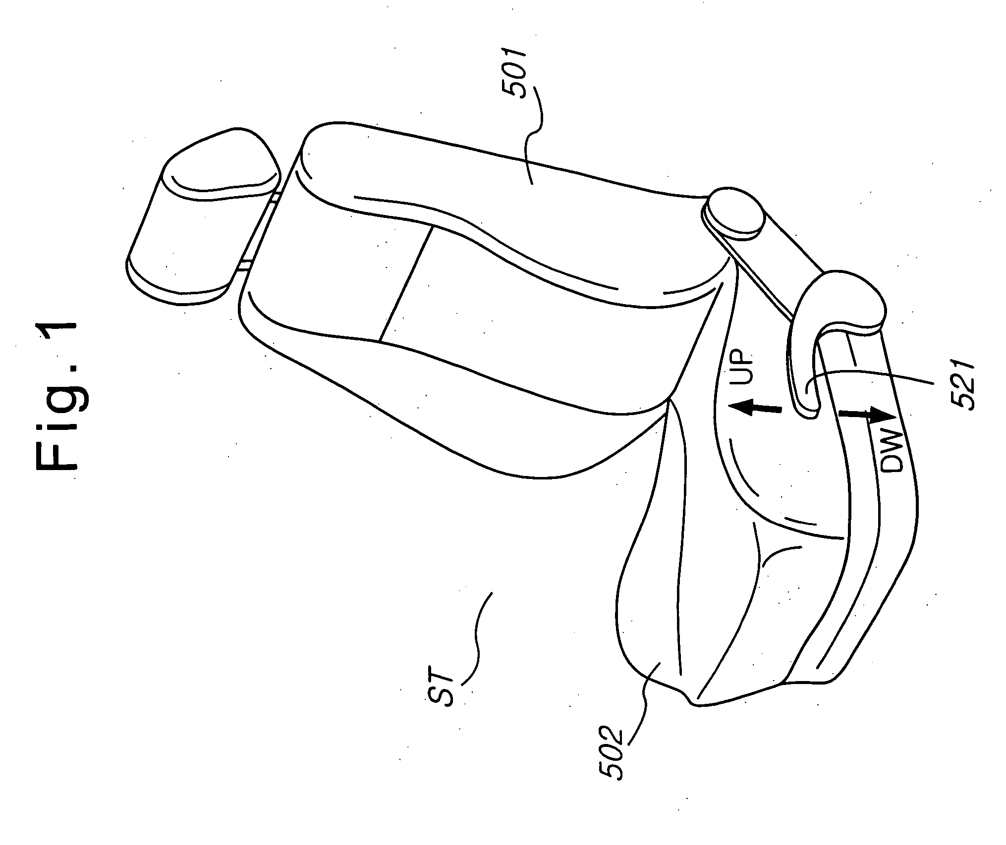
[0033] A seat cushion pumping device for a vehicle in accordance with the present invention will be explained with reference to FIGS. 1 to 12.

[0034] In a seat ST consisting of a seat back 501 and a seat cushion 502, link means is installed on front and rear portions of a lower surface of the seat cushion 502, and is adapted to allow a height of the seat cushion 502 to be adjusted as desired, and gears are provided on the link means for the operation thereof. A pumping device is engaged with the gears for rotating them in forward and rearward directions, thereby functioning to adjust the height of the seat cushion 502.

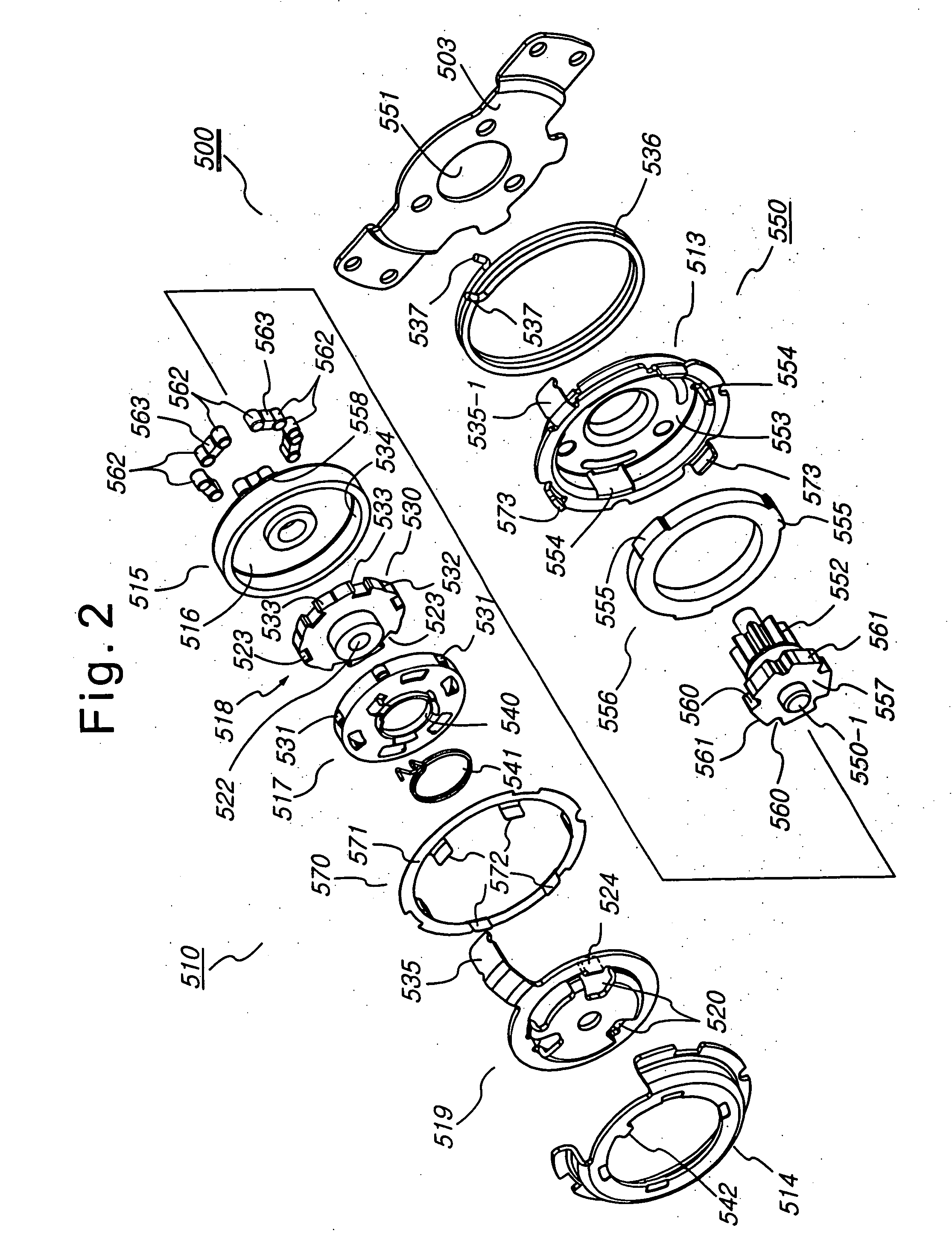
[0035] The pumping device in accordance with the present invention, d...


PUM


Abstract

Disclosed herein is a seat cushion pumping device for a vehicle adapted to adjust a height of a seat cushion. The seat cushion pumping device comprises a clutch unit adapted to transmit a rotating force to gears of link means in a desired direction where the seat cushion is to be moved, and a brake unit for fixing the operated link means so as not to move. The clutch unit and the brake unit are accommodated between a lower bracket and an upper bracket, which are positioned in front of a mounting bracket for accommodating the entire pumping device there between.

Description

[0001] This application claims priority of pending Korean Patent Application No. 2003-0047547 filed Jul. 12, 2003. BACKGROUND OF THE INVENTION [0002] 1. Field of the Invention [0003] The present invention relates to a seat cushion pumping device for a vehicle, and more particularly to an improved pumping device, which is adapted to adjust a height of a vehicle seat cushion in conformity with the body shape of a driver or passenger. [0004] 2. Description of the Related Art [0005] As well known to those skilled in the art, a pumping device for a vehicle functions to adjust a height of a seat cushion constituting a vehicle seat in conformity with the body shape of a driver or passenger. [0006] Various seat cushion pumping devices have been developed and used. The applicant of the present invention also had developed various kinds of pumping devices including a drum brake, and had filed one of them in the Korean Industrial Property Office as Serial No. 10-2002-013741. Now, a conventiona...

Claims


Application Information

Patent Timeline
Patent Type & Authority Applications(United States)
IPC IPC(8): B60N2/16F16D63/00
CPCB60N2/167F16D63/006B60N2/168B60N2/16
Inventor KIM, JAE-HO
Owner DAS CO LTD
Why Eureka
Try Eureka